Module Performance
The total electrical power output (wattage) of a photovoltaic module is equal to its operating voltage multiplied by its operating current. Photovoltaic modules may produce current over a wide range of voltages. This is unlike voltage sources such as batteries, which produce current at a relatively constant voltage.
The output characteristics of any given module are characterized by a performance curve, called an I-V curve, that shows the relationship between current and voltage output. The chart shows a typical I-V curve. Voltage (V) is plotted along the horizontal axis. The current is plotted along the vertical axis. Most I-V curves are given for the standard test conditions (STC) of 1,000 watts per square meter irradiance (often referred to as one peak sun) and 25°C (07°F) cell temperature. It should be noted that STC represent the optimal conditions as a consistent means for measuring — rarely are these conditions recreated in outside environments. The IV curve contains three significant points:
- Maximum Power Point (both Vmp and Imp)
- Open Circuit Voltage (Voc)
- Short Circuit Current (Isc)
1. Maximum Power Point (Vmp & Imp)
This point, labeled Vmp and Imp, is the operating point at which the maximum output will be produced by the module at operating conditions indicated for that curve. In other words, the Vmp and Imp of the module can be measured when the system is under load at 25°C cell temperature and 1,000 watts per square meter. The voltage at the maximum power point can be determined by extending a vertical line from the curve downward to read a value on the horizontal voltage scale. The example in the chart above displays a voltage of approximately 17 volts at the maximum power (Vmp). The current at the maximum power point can be determined by extending a horizontal line from the curve to the left to read a value on the vertical current scale (Imp). The example above displays a current of approximately 2.5 amps at the maximum power.
The wattage at the maximum power point is determined by multiplying the voltage at maximum power by the current at maximum power. In the chart, the maximum wattage at STC would be approximately 43 watts. This power is represented by the rectangle under the curve.
The power output decreases as the voltage drops. Current and power output of most modules drops off as the voltage increases beyond the maximum power point.
2. Open Circuit Voltage (Voc)
This point, labeled Voc, is the maximum potential voltage achieved when no current is being drawn from the module. Since no current is flowing, the module experiences maximum electrical pressure. The example at left displays an open circuit voltage of approximately 21 volts. The power output at Voc is zero watts. Open Circuit Voltage can be measured in the field in several common circumstances. When buying a module, it is recommended to test the voltage to see if it matches the manufacturers specifications. When testing voltage with a digital multi-meter from the positive to the negative terminal, an open circuit is created by the meter which allows Voc to be measured. It is also common to see a module operating at Voc early in the morning and late in the evening.
3. Short Circuit Current (Isc)
This point, labeled Isc, is the maximum current output that can be reached by the module under the conditions of a circuit with no resistance or a short circuit. The example to the left displays a current of approximately 2.65 amps. The power output at Isc is zero watts. When first purchasing a module, it is recommended to test the short circuit current to see if it matches the specification sheet. The short circuit current can be measured only when making a direct short across the positive and negative terminals of a module. Creating a direct short across more than one module at a time (or a module with voltage greater than 24V nominal) is not recommended and can be extremely dangerous. All Isc measurements should be taken when the module is not connected to other components in the system.
Note: When testing modules with ‘quickconnects’ it is recommended to use test leads to avoid leaving carbon deposits (which cause high resistance) on the module’s leads. Before testing amperage with a digital multi-meter, check to ensure the module’s Isc does not exceed the meter’s DC amperage rating and always use the appropriate personal protective equipment.
4. Specification Label
All of the values found on the I-V curve above are used to create a specification label for each module. All modules are rated under standard test conditions, thereby allowing their values to be compared. The specification label can be found on the back side of the module or through the manufacturer.
Source: “PHOTOVOLTAICS - Design and Installation Manual” by Solar Energy International.
Solar Certification Training from Professional Solar Installers
With 18 IREC-ISPQ Certified Solar Photovoltaic Trainers and 24 NABCEP Certified Solar PV Installers — more than any other solar training organization — Solar Energy International's experienced team is on the forefront of renewable energy education. If you are seeking online solar training or in-person lab training for the NABCEP Entry Level Exam or NABCEP Installer Certification, why not receive your education from a team of the most experienced solar installer professionals in the industry? Many SEI trainers have participated in the most notable solar installations within their communities stateside, and in the developing world.
To start your solar training path today with Solar Energy International, click here.
Series and Parallel Circuits in Power Sources
Photovoltaic modules and batteries are a system's building blocks. While each module or battery has a rated voltage or amperage, they can also be wired together to obtain a desired system voltage.
1. Series Circuits
Series wiring connections are made at the positive (+) end of one module to the negative (-) end of another module. When loads or power sources are connected in series, the voltage increases. Series wiring does not increase the amperage produced. The image at right shows two modules wired in series resulting in 24V and 3A.
Series circuits can also be illustrated with flashlight batteries. Flashlight batteries are often connected in series to increase the voltage and power a higher voltage lamp than one battery only could power alone.
Question: When four 1.5V DC batteries are connected in series, what is the resulting voltage?
Answer: 6 volts
2. Parallel Circuits
Parallel wiring connections are made from the positive (+) to positive (+) terminals and negative (-) to negative (-) terminals between modules. When loads or sources are wired in parallel, currents are additive and voltage is equal through all parts of the circuit. To increase the amperage of a system, the voltage sources must be wired in parallel. The image at right shows PV modules wired in parallel to get a 12V, 6-amp system. Notice that parallel wiring increases the current produced and does not increase voltage.
Batteries are also often connected in parallel to increase the total amp-hours, which increases the storage capacity and prolongs the operating time.s
3. Series and Parallel Circuits
Systems may use a mix of series and parallel wiring to obtain required voltages and amperages. The image at right shows four 3-amp, 12 VDC modules wired in series and parallel. Strings of two modules are wired in series, increasing the voltage to 24V. Each of these strings is wired in parallel to the circuit, increasing the amperage to 6 amps. The result is a 6-amp, 24 VDC system.
4. Batteries in Series and Parallel
The advantages of a parallel circuit can be illustrated by observing how long a flashlight will operate before the batteries fully discharge. To make the flashlight last twice as long, battery storage would have to be doubled.
In the picture to the left, a series string of four batteries has been added in parallel to another string of four batteries to increase storage (amp-hours). The new string of batteries is wired in parallel, which increases the available amp-hours, thereby adding additional storage capacity and increasing the usage time. The second string could not be added in series because the total voltage would be 12 volts, which is not compatible with the 6-volt lamp.
5. High Voltage PV Arrays
So far in this chapter, we have only discussed input voltages up to 24V nominal. Today, most battery-less grid-tied inverters on the market require a high voltage DC input. This input window is generally in the range of 350 to 550 VDC. Because of the inverter's high voltage input requirements, PV modules must be wired together in series in order to sufficiently increase the voltage.
6. Series and Parallel Wiring Examples & Instructions
1. Connect the photovoltaic modules (array) either in series or parallel to get the desired system voltage.
2. Calculate total module output for volts and amps.
3. Connect the array to a charge controller.
4. Connect batteries either in series or parallel to get the desired system voltage.
5. Calculate total battery bank voltage and amp-hour capacity.
6. Connect the battery bank to the charge controller.
Source: “PHOTOVOLTAICS - Design and Installation Manual” by Solar Energy International.
Solar Certification Training from Professional Solar Installers
With 18 IREC-ISPQ Certified Solar Photovoltaic Trainers and 24 NABCEP Certified Solar PV Installers — more than any other solar training organization — Solar Energy International's experienced team is on the forefront of renewable energy education. If you are seeking online solar training or in-person lab training for the NABCEP Entry Level Exam or NABCEP Installer Certification, why not receive your education from a team of the most experienced solar installer professionals in the industry? Many SEI trainers have participated in the most notable solar installations within their communities stateside, and in the developing world.
To start your solar training path today with Solar Energy International, click here.
How Grid-Tied Solar Works
The basic components of a grid-tied solar system are rooftop modules, an inverter and a utility meter.
![]() Solar Modules:
Solar Modules:
Solar modules collect the sun’s energy and convert it to electricity.
![]() The Inverter:
The Inverter:
The inverter converts the electricity from direct current (DC) to alternating current (AC), which enters the electrical panel. This distributes the electricity load to all lights, appliances etc.
![]() The Utility Meter:
The Utility Meter:
The utility meter displays the amount of power you use or produce. Any power not used is fed back to the grid.
Photovoltaic System Types
Photovoltaic systems can be configured in many ways. For example, many residential systems use battery storage to power appliances during the night. In contrast, water pumping systems often operate only during the day and require no storage device. A large commercial system would likely have an inverter to power AC appliances, whereas a system in a small cabin would likely power only DC appliances and wouldn't need an inverter. Some systems are linked to the utility grid, while others operate independently.
1. Day Use Systems
The simplest and least expensive photovoltaic systems are designed for day use only. These systems consist of modules wired directly to a DC appliance, with no storage device. When the sun shines on the modules, the appliance consumes the electricity they generate. Higher insolation (sunshine) levels result in increased power output and greater load capacity.
Examples of day use systems include:
- Remote water pumping for a storage tank
- Operation of fans, blowers, or circulators to distribute thermal energy for solar water heating systems or ventilation systems
2. Direct Current Systems Powering Alternating Current Loads
Photovoltaic modules produce DC electrical power, but many common appliances require AC power. Direct current systems that power AC loads must use an inverter to convert DC electricity into AC. Inverters provide convenience and flexibility in a photovoltaic system, but add complexity and cost. Because AC appliances are mass-produced, they are generally offered in a wider selection, at lower cost, and with higher reliability than DC appliances. High quality inverters are commercially available in a wide range of capacities.
3. Direct Current Systems with Storage Batteries
To operate loads at night or during cloudy weather, PV systems must include a means of storing electrical energy. Batteries are the most common solution. System loads can be powered from the batteries during the day or night, continuously or intermittently, regardless of weather.
In addition, a battery bank has the capacity to supply highsurge currents for a brief period, giving the system the ability to start large motors or to perform other difficult tasks. A simple DC system that uses batteries is illustrated below. This system’s basic components include: PV modules, charge controllers storage, batteries, and appliances (the system’s electrical load).
A battery bank can range from small flashlight size batteries to dozens of heavy-duty industrial batteries. Deep-cycle batteries are designed to withstand being deeply discharged and then fully recharged when the sun shines. (Conventional automobile batteries are not well suited for use in photovoltaic systems and will have short effective lives). The size and configuration of the battery bank depends on the operating voltage of the system and the amount of nighttime usage. In addition, local weather conditions must be considered in sizing a battery bank. The number of modules must be chosen to adequately recharge the batteries during the day.
Batteries must not be allowed to discharge too deeply or be overcharged - either situation will damage them severely. A charge controller will prevent the battery from overcharging by automatically disconnecting the module from the battery bank when it is fully loaded. Some charge controllers also prevent batteries from reaching dangerously low charge levels by stopping the supply of power to the DC load. Providing charge control is critical to maintaining battery performance in all but the simplest of PV systems.
4. Hybrid Systems
Most people do not run their entire load solely off their PV system. The majority of systems use a hybrid approach by integrating another power source. The most common form of hybrid system incorporates a gas or diesel-powered engine generator, which can greatly reduce the initial cost. Meeting the full load with a PV system means the array and batteries need to support the load under worst-case weather conditions. This also means the battery bank must be large enough to power large loads, such as washing machines, dryers, and large tools. A generator can provide the extra power needed during cloudy weather and during periods of heavier than normal electrical use, and can also be charging the batteries at the same time. A hybrid system provides increased reliability because there are two independent charging systems at work.
Another hybrid approach is a PV system integrated with a wind turbine. Adding a wind turbine makes sense in locations where the wind blows when the sun doesn't shine. In this case, consecutive days of cloudy weather are not a problem, so long as the wind turbine is spinning. For even greater reliability and flexibility, a generator can be included in a PV/Wind system. A PV/Wind/Generator system has all of the advantages of a PV/Generator system, with the added benefit of a third charging source for the batteries.
5. Grid-Tied Systems
We offer extensive experience and the highest quality components for grid-tied solar systems, a system connected to the electrical grid, allowing the customer to use the electricity from the grid as a back-up. Should your customer’s needs be unique, our team can design a system that reflects customer requirements and site specifications.
Photovoltaic systems that are connected to the utility grid (utility-connected, grid-tied, or line-tied systems) do not need battery storage in their design because the utility grid acts as a power reserve. Instead of storing surplus energy that is not used during the day, the homeowner sells the excess energy to a local utility through a specially designed inverter. When homeowners need more electricity than the photovoltaic system produces, they can draw power from the utility grid.
If the utility grid goes down, the inverter automatically shuts off and will not feed solar-generated electricity back into the grid. This ensures the safety of line persons working on the grid. Because utility-connected systems use the grid for storage, these systems will not have power if the utility grid goes down. For that reason, some of these systems are also equipped with battery storage to provide power in the event of power loss from the utility grid.
The Public Utilities Regulatory Policies Act (PURPA) of 1978 requires electric utilities to purchase power from qualified, small power producing system owners. The utilities must pay the small power producers based on their "avoided costs," or costs the utility does not have to pay to generate that power themselves. Additional terms and conditions for these purchases are set by state utility commissions and vary from state to state. While this law allows homeowners in areas with utility power to purchase photovoltaic systems and sell their excess power to an electric utility, people contemplating doing so should remember that this is rarely a profitable venture at the present time.
Some utility companies offer “net metering” to their customers, where a single meter spins in either direction depending upon whether the utility is providing power to the customer or the customer is producing excess power. The customer or independent power producer pays or collects the net value on the meter. Net metering is very desirable to the independent power producer because he/she can sell power at the same retail rate that the utility charges its customers.
6. Off-Grid
Just as our experience is extensive in grid-tied solar, so it is in off-grid, a stand-alone solar electricity generating system. We provide the knowledge, as well as the components, for off-grid solar systems. We can also design systems that accommodate virtually every type of remote location.
Off-Grid Introduction
By definition an off-grid power system is any system that provides power where utility power is unavailable. Off-Grid systems typically make financial sense any place where the utility would have to run lines more than one half of a mile for grid connection. In addition, the new federal PV incentive does not distinguish between grid-tied and off-grid, so any system should be eligible for a federal tax rebate.
A typical off-grid system typically consists of an off-grid inverter, batterybank, generator, and a DC power source (PV, Wind, Micro Hydro, etc.). If a PV array is used as a DC power source then a charge controller would also be used to harvest energy from the solar array and protect the batteries from overcharging.
System sizing is much more important on an off-grid system than a gridtied system. Here are the questions that need to be answered:
- How many kWh do you expect to consume?
- How many hours/days of autonomy do you want to be able to run without PV (or other energy source)?
- What is the largest load that you need to run? How much power is required to start this load?
- What is your budget?
Off-Grid Inverters
There are a number of things to consider when choosing an off-grid inverter:
Tare Losses
Tare losses are the power that is required to run the system in standby mode. Every watt is precious in an off-grid system and reducing power wasted is critical. This is a specification to look at very closely since there is a wide variance among different inverter manufacturers for tare losses. In addition, some inverter companies have the ability to turn off inverters entirely in multiple inverter systems to further reduce tare losses.
Surge Capability
The ability of an inverter to surge to a higher level than its rated output for a short duration to start large loads like well pumps is critical. The specifications that should be looked at are the Maximum Output Current and the AC Overload capability. If there are large loads a good number to look for is a five second surge capability of at least 1.5 times the rated...
Michael G 8.06kW Grid-Tied Roof Mount
Project Description
Canadian Solar CS6X-310P Solar Panels, SolarEdge SE7600A-US-U Inverter with P400-2NM4ARM Power Optimizers, IronRidge XR-100 Rails with RS-GD-MCL-225 Grounding Mid Clamps, 29-7000-157 End Clamps, 51-7240-040 Tilt Legs and RS-LFT-001 Slotted L-Feet, Quick Mount PV QMSE A 1 E-Mount.
Customer Comments
"I designed, purchased, permitted through Jeffco, contracted with XCEL, hired a competent friend who is a handy man and installed. First full year, we met our demand exactly. This year I was a bit short. Considering adding capacity. With DC/DC converters, we were able to have multiple exposures."
Project Photos
Project Components
| Qty | Item # | Description | |
| 26 | 1120-081 | Canadian Solar CS6X-310P-PT Solar Panel Pallet | |
| 1 | 1430-186 | SolarEdge SE7600A-US-U Inverter | |
| 26 | 1460-016 | SolarEdge P400-2NM4ARM Power Optimizer | |
| 13 | 1340-220 |  | IronRidge 29-5003-005 Mounting Kit for Enphase ** Clearance Item - All Sales Final ** |
| 8 | 1340-784 | IronRidge XR-100-SPLC Splice Kit | |
| 5 | 1340-008 | IronRidge 29-7000-157 End Clamp | |
| 11 | 1340-675 | IronRidge RS-GD-MCL-225 Grounding Mid Clamp | |
| 1 | 1340-787 |  | IronRidge XR-100-CAP End Cap |
| 5 | 1340-051 | IronRidge 51-7240-040 Tilt Leg Kit | |
| 6 | 1340-774 |  | IronRidge XR-100-132A Rail |
| 8 | 1340-776 |  | IronRidge XR-100-168A Rail |
| 16 | 1330-789 | IronRidge RS-LFT-001 Slotted L-Foot Kit | |
| 2 | 1340-209 |  | IronRidge 29-4000-077 Wire Clip |
| 4 | 1340-681 | IronRidge RS-GDST-001 Grounding Strap | |
| 5 | 2040-026 | IronRidge RS-GDLG-002 Grounding Lug | |
| 61 | 1330-798 |  | Quick Mount PV QMSE A 1 E-Mount |
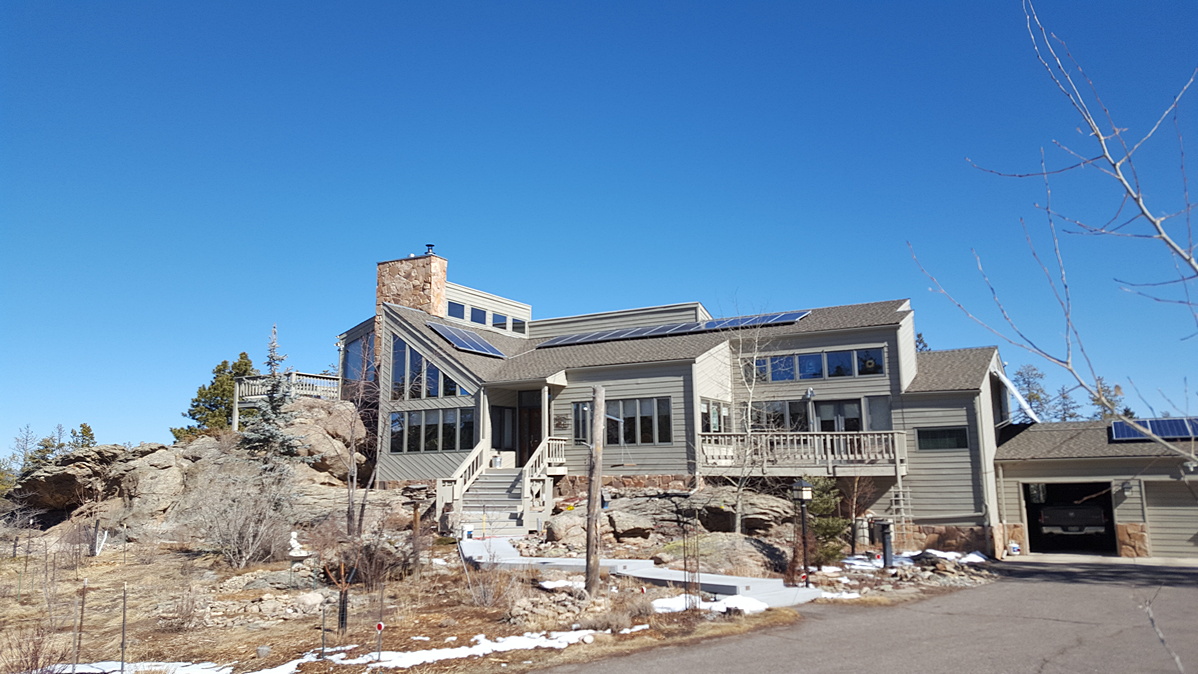
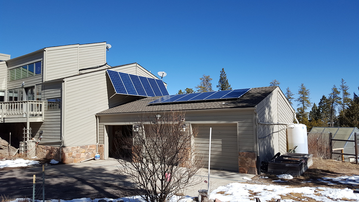
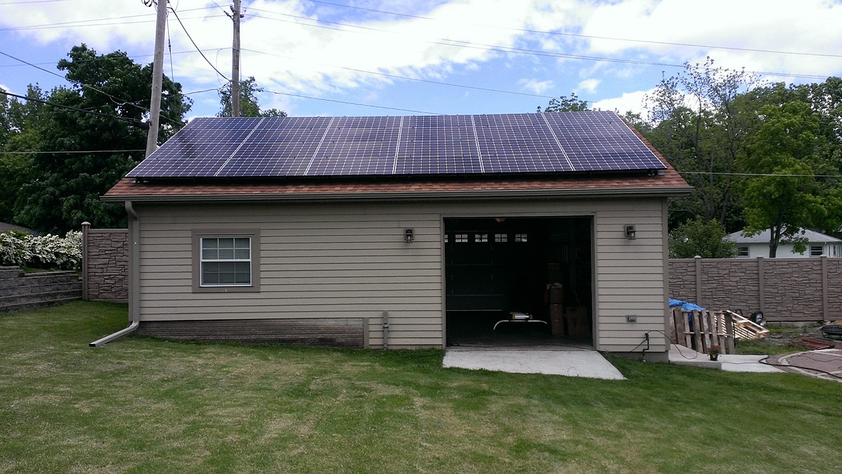
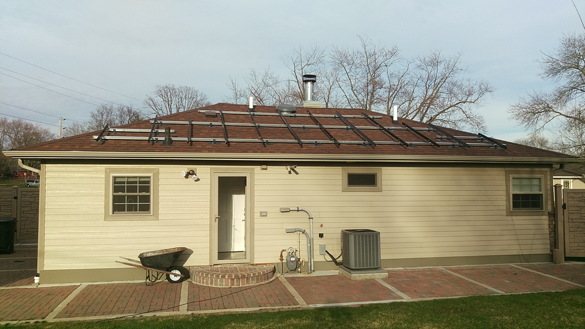
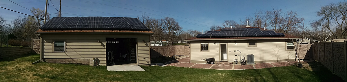
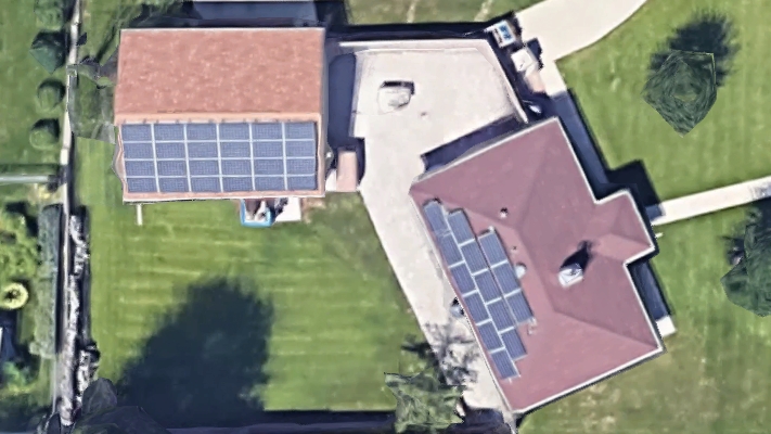
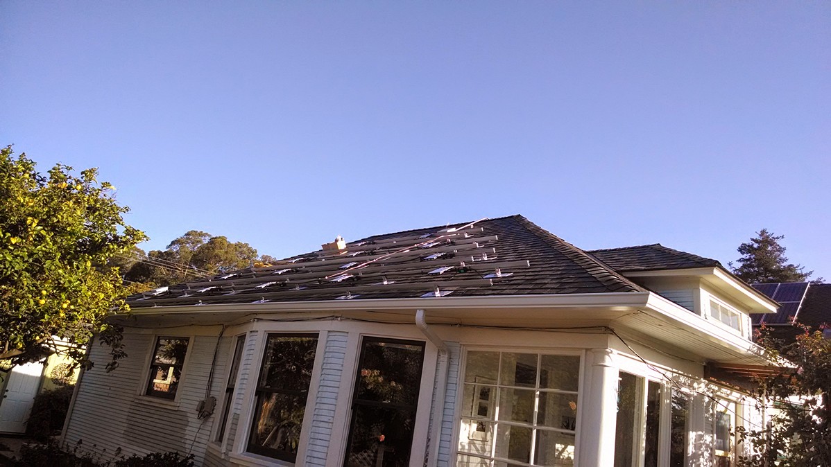
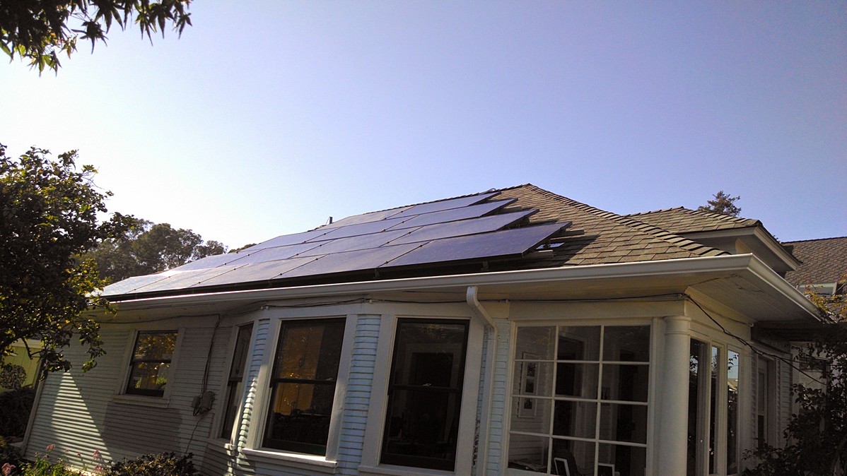
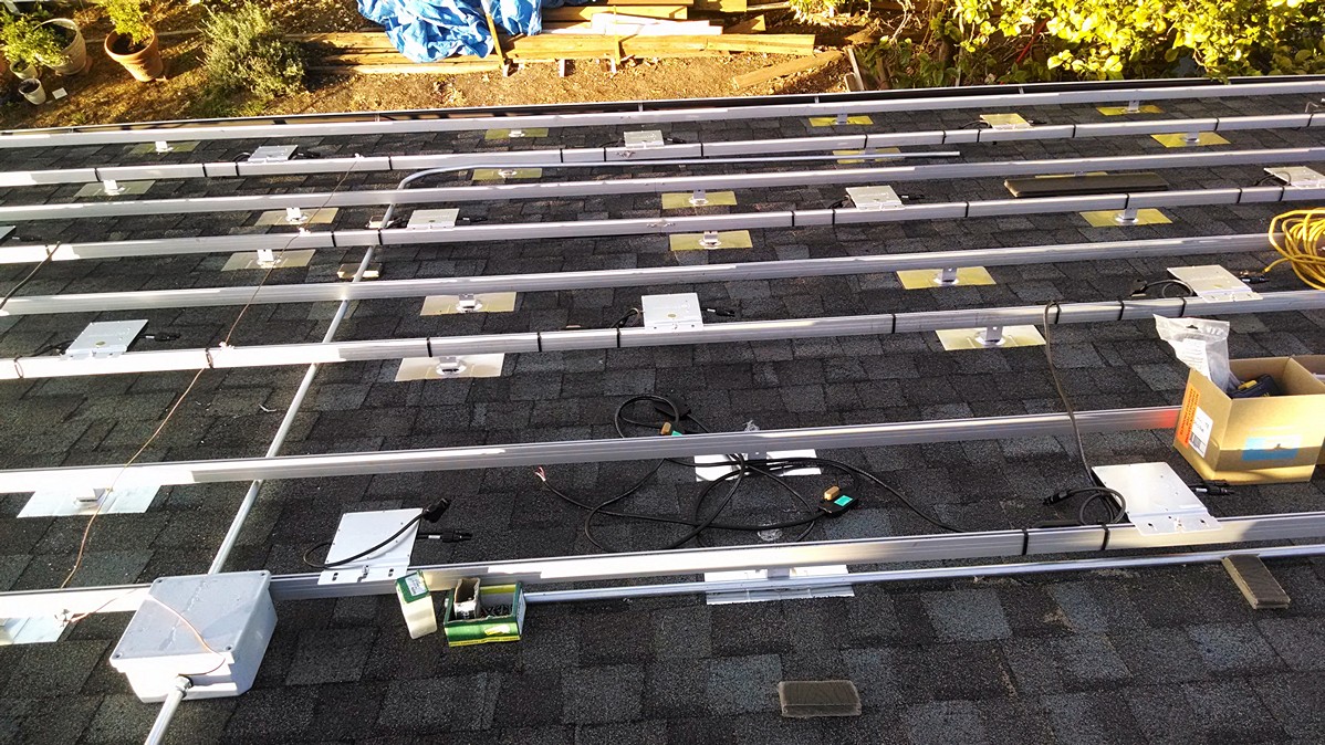
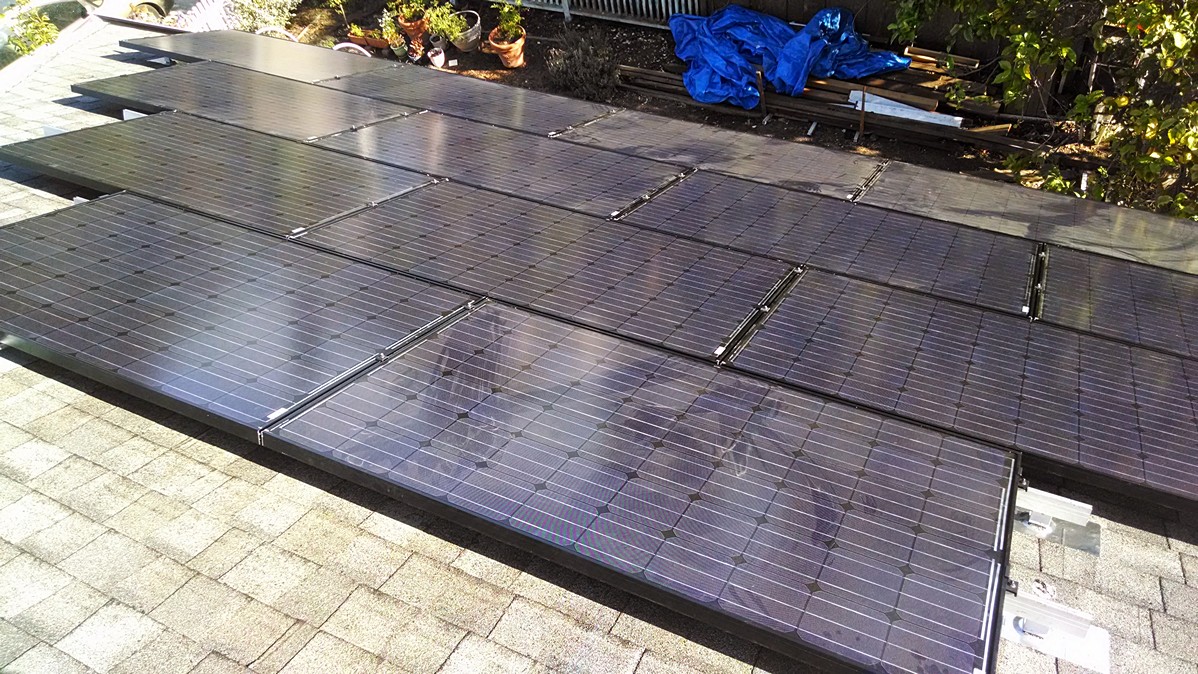
Paul Y 9.92kW Grid-Tied Roof Mount
Project Description
LG305N1C-B3 and LG320N1C-G4 Solar Panels, Enphase M250-60-2LL-S22 and S280-60-LL-2-US Microinverters with ENV-120-01 Envoy Communications Gateway, Unirac 2" Square Tubing with IronRidge XR-100 Rails, Grounding Mid Clamps, 29-7000 End Clamps and RF-FLSH-001B Flashfeet.
Customer Comments
"I installed a 6kw system on the garage in the spring of 2015 and added another 3.92kw to the house in the spring of 2016. I used the Unirac 2" square tubing to help elevate the panels off the roof more for cooling and also so I could choose where the feet anchored into the roof (I hit cross bracing instead of the rafters)."
Project Photos
Project Components
| Qty | Item # | Description | |
| 24 | 1100-216 | LG Electronics LG305N1C-B3 Solar Panel | |
| 1 | 1410-028 |  | Enphase ET-INSTL Install Kit |
| 12 | 2040-022 |  | IronRidge 29-4000-002 WEEB Grounding Lug |
| 10 | 2010-027 |  | Heyco M3231 Strain Relief |
| 2 | 1330-658 |  | Oatey 12801 Flashing |
| 5 | 1310-710 | UniRac 403202C U-LA 2" Brace | |
| 60 | 2040-023 |  | IronRidge 29-4000-001 WEEB DMC Compression Clip |
| 2 | 1980-021 |  | Hellermann 596-00243 Label |
| 2 | 1980-013 |  | Hellermann 596-00235 Label |
| 12 | 1330-790 |  | IronRidge RS-LFT-001B Slotted L-Foot Kit ** Clearance Item - All Sales Final ** |
| 7 | 1310-708 |  | UniRac 403201C U-LA 2" Brace |
| Qty | Item # | Description | |
| 20 | 1410-025 |  | Enphase ET17-240-BULK Engage AC Trunk Cable |
| 10 | 1430-219 | Enphase S280-60-LL-2-US Microinverter | |
| 8 | 1340-777 |  | IronRidge XR-100-168B Rail |
| 50 | 2040-023 | | IronRidge 29-4000-001 WEEB DMC Compression Clip |
| 16 | 2040-022 | | IronRidge 29-4000-002 WEEB Grounding Lug |
| 1 | 1980-021 | | Hellermann 596-00243 Label |
| 3 | 1980-013 | | Hellermann 596-00235 Label |
| 8 | 1330-790 | | IronRidge RS-LFT-001B Slotted L-Foot Kit ** Clearance Item - All Sales Final ** |
| 1 | 1330-770 | IronRidge RF-FLSH-001B Flashfoot | |
| 4 | 1340-209 | | IronRidge 29-4000-077 Wire Clip |
| 6 | 2040-026 | IronRidge RS-GDLG-002 Grounding Lug | |
| 7 | 1340-007 | IronRidge 29-7000-157B End Clamp | |
| 7 | 1340-674 |  | IronRidge RS-GD-MCL-225B Grounding Mid Clamp ** Clearance Item - All Sales Final ** |
| 1 | 1340-787 | | IronRidge XR-100-CAP End Cap |
| Qty | Item # | Description | |
| 10 | 1330-770 | IronRidge RF-FLSH-001B Flashfoot | |
| 5 | 1340-209 | | IronRidge 29-4000-077 Wire Clip |
| 3 | 1340-015 |  | IronRidge 29-7000-204B End Clamp ** Clearance Item - All Sales Final ** |
| 2 | 2040-026 | IronRidge RS-GDLG-002 Grounding Lug | |
| 2 | 1340-681 | IronRidge RS-GDST-001 Grounding Strap | |
| 12 | 1340-678 | IronRidge RS-GD-MCL-275B Grounding Mid Clamp | |
| 6 | 1340-784 | IronRidge XR-100-SPLC Splice Kit | |
| 6 | 1340-779 |  | IronRidge XR-100-204B Rail |
| 6 | 1340-777 | | IronRidge XR-100-168B Rail |
| 1 | 1340-787 | | IronRidge XR-100-CAP End Cap |
| Qty | Item # | Description | |
| 4 | 1430-219 | Enphase S280-60-LL-2-US Microinverter | |
| 6 | 1410-022 |  | Enphase ET-SEAL-10 Water Tight Cap |
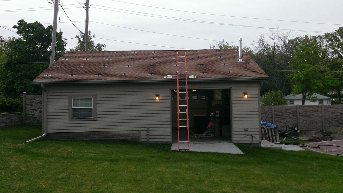
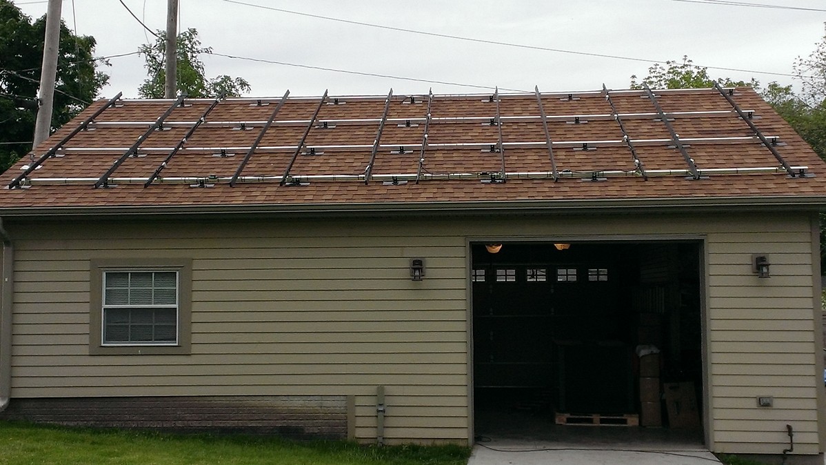
Damien P 5.3kW Grid-Tied Roof Mount
Project Description
Suniva OPT265-60-4-1B0 Solar Panels, Enphase M250-60-2LL-S22 Microinverters with Envoy Communications Gateway, IronRidge XRL Rails, RF-FLSH-001 FlashFeet, RS-GD-MCL-225B Grounding Mid Clamps and 29-7000-157B End Clamps.
Project Photos
Project Components
| Qty | Item # | Description | |
| 20 | 1110-171 | Suniva OPT265-60-4-1B0 Solar Panel | |
| 20 | 1430-160 | Enphase M250-60-2LL-S22 Microinverter | |
| 2 | 1410-023 |  | Enphase ET-TERM-01 Branch Terminator |
| 4 | 1410-022 | | Enphase ET-SEAL-10 Water Tight Cap |
| 1 | 1410-036 |  | Enphase ET-DISC-05 Cable Disconnect Tool |
| 24 | 1410-025 | | Enphase ET17-240-BULK Engage AC Trunk Cable |
| 9 | 1340-053 | IronRidge 51-6000-144A XRL Rail | |
| 4 | 1340-055 | IronRidge 51-6000-168A XRL Rail | |
| 3 | 1340-209 | | IronRidge 29-4000-077 Wire Clip |
| 4 | 1340-060 | IronRidge 29-7000-000 XRL Splice Kit | |
| 7 | 1340-007 | IronRidge 29-7000-157B End Clamp | |
| 9 | 1330-769 | IronRidge RF-FLSH-001 FlashFoot | |
| 7 | 1340-674 | | IronRidge RS-GD-MCL-225B Grounding Mid Clamp ** Clearance Item - All Sales Final ** |
| 1 | 1340-681 | IronRidge RS-GDST-001 Grounding Strap | |
| 4 | 1340-059 | IronRidge 51-6000-216A XRL Rail | |
| 1 | 2040-002 |  | Amphenol HGLU-10 HelioLug |
| Qty | Item # | Description | |
| 1 | 2140-018 | Enphase ENV-120-01 Envoy Communications Gateway | |
| 1 | 1410-023 | | Enphase ET-TERM-01 Branch Terminator |
| Qty | Item # | Description | |
| 2 | 1340-226 | IronRidge 29-4000-088 End Caps | |
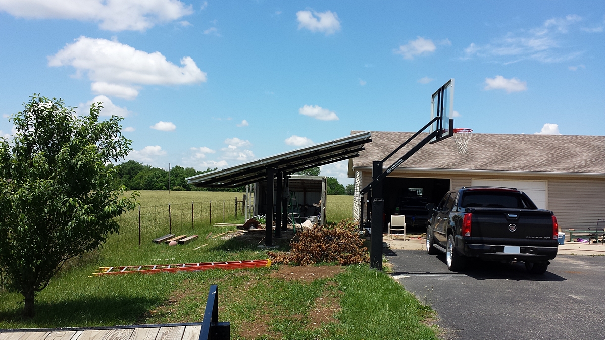
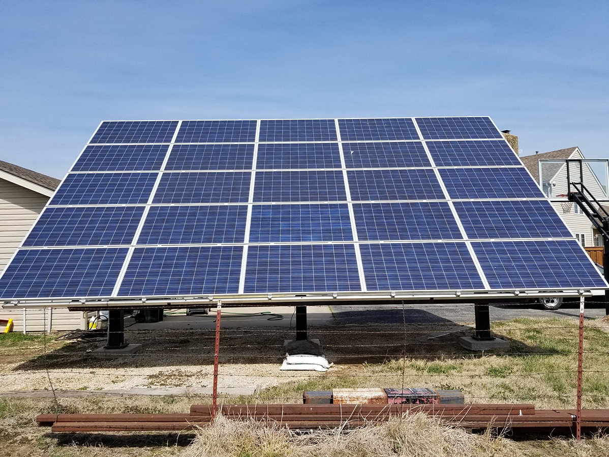
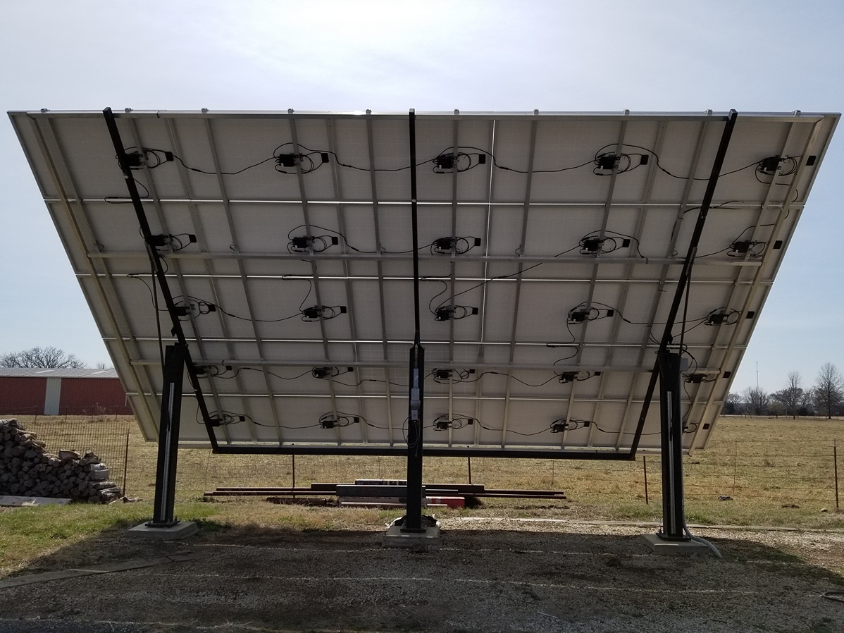
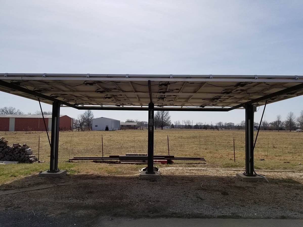
Shawn B 6.375kW Grid-Tied Ground Mount
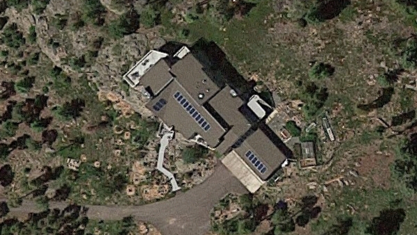
Project Description
Astronergy CHSM6610PR-255 Solar Panels, SolarEdge SE6000A-US Inverter with OP300-MV-MC4SM-2NA Power Optimizers, Square D DU222RB AC Disconnect, ProSolar R-136 Standard Support Rails with A-SPLICE-1 Splice Kits, C-225IMC-1 Mid Clamps, C-1572EC-1 End Clamps and P-CN-1 Channel Nuts.
Customer Comments
"I supplied the 7" square post, 2x4 steel tubing, 2x2 aluminum tubing, and linear actuator to build the framework for the solar mounting track. I am a locomotive engineer by trade but started learning fabrication when in high school and learned more as i got older. Also learning electrical and plumbing as I worked in construction in my early twenties."
Project Photos
Project Components
| Qty | Item # | Description | |
| 25 | 1120-039 | Astronergy CHSM6610PR-255-PT Solar Panel Pallet | |
| 25 | 1450-074 | SolarEdge OP300-MV-MC4SM-2NA Power Optimizer | |
| 1 | 1430-143 | SolarEdge SE6000A-US Inverter | |
| 1 | 1940-020 |  | Square D DU222RB AC Disconnect |
| 70 | 1340-077 |  | ProSolar P-CN-1 Channel Nut |
| 20 | 1340-222 |  | ProSolar A-EZECAP-1 End Cap |
| 20 | 1340-095 | ProSolar C-1572EC-1 End Clamp | |
| 40 | 1340-124 | ProSolar C-225IMC-1 Mid Clamp | |
| 10 | 1340-130 | ProSolar A-SPLICE-1 Splice Kit | |
| 20 | 1330-131 |  | ProSolar R-136 Standard Support Rail |
| 35 | 2040-018 |  | Wiley Electronics WEEB-PMC Grounding Clip |
| 10 | 2040-011 |  | Wiley Electronics WEEB-BNDJMP6.7 Bonding Jumper |
| 10 | 2040-021 |  | Wiley Electronics WEEB-LUG-6.7 Grounding Lug |
| 2 | 2040-010 |  | Wiley Electronics WEEB-ACC-PV Cable Clip |
| 6 | 2010-012 |  | Multi-Contact 32.0016P0001-UR MC4 Connector |
| 6 | 2010-013 |  | Multi-Contact 32.0017P0001-UR MC4 Connector |
| 1 | 2010-015 |  | Falcon 10-7-500-dbl Black PV Wire |
Solar Module Ratings - STC vs PTC
STC (Standard Test Condtions) and PTC (PVUSA Test Conditions) are two methods of testing module performance. For instance, a Candaian Solar CS3K-320MS has an STC rating (nameplate value) of 320W and a PTC rating of 298.1W. The difference in the ratings is largely attributed to the effect of temperature change on module output. STC uses a steady temperature of 25° Celsius, whereas PTC uses a temperature of 20° Celsius combined with a calculation to measure module performance.

The PTC formula was developed by a California-based solar research and development partnership between the US Department of Energy and several major utilities. This group was established in 1986 and was known as Photovoltaics for Utility Scale Applications (PVUSA). They merged with the California Energy Commission in 1997 and ultimately dissolved in 2000. Although PVUSA no longer exists, their method of rating module performance was found to be more accurate than the STC rating system and is still in use today.
Because STC fails to measure the effect of temperature change on the cells, an overly optimistic electricity output results. The PTC system collects data on a module’s power output for a designated period of time under conditions of 1,000 Watts per square meter solar irradiance, 20° Celsius air temperature, and a wind speed of one meter per second at 10 meters above ground level. The cell temperature is combined with the temperature coefficient of power to measure the voltage change in the cell relative to the temperature change. The outcome of this test generates the PTC rating and thereby a more accurate "real-world" performance result.
Project designers and solar module purchasers should use the difference between STC and PTC to determine which modules will deliver the maximum amount of energy and fastest return on investment. When comparing modules of equal STC ratings and different PTC ratings, the panel with the higher PTC value will produce more on-site solar energy per-watt installed and a more accurate expected power output.
Welcome to RES Supply – where you can always find Renewable Energy Systems for less. We have been offering the world’s best alternative energy products at the lowest possible price since 2012. Year after year, we have been driven by a strong commitment to deliver exceptional value for our customers and earn their repeat business in return.
We are proud that our longevity and growth have occurred organically, without the use of social media, email promotions or solicited reviews. Instead, we have found that our customers appreciate our focus on cost reduction far more than relentless marketing. We value your time, respect your privacy and are truly grateful for your business.
 |  |
Warehouse LocationsArizona, California, Florida, Illinois, Massachusetts, Minnesota, Nevada, New Jersey and TexasWith distribution partners located throughout the US, you can be assured of timely shipments. | |
If you are new to RESsupply.com, take a moment to discover more about Renewable Energy Systems in our Learning Center, receive help planning your project in our Design section, ask our Solar Assistant, Ray, for installation assistance, look for great savings in our Deals department, and of course, locate the most dependable products from the industry's leading manufacturers throughout our site.
If you would like additional information about a product you see on our site, click on the Have a Question About This Product? link found directly under the price. If you need to contact us, return a product, read frequently asked questions, or review our terms and conditions, use the following links: