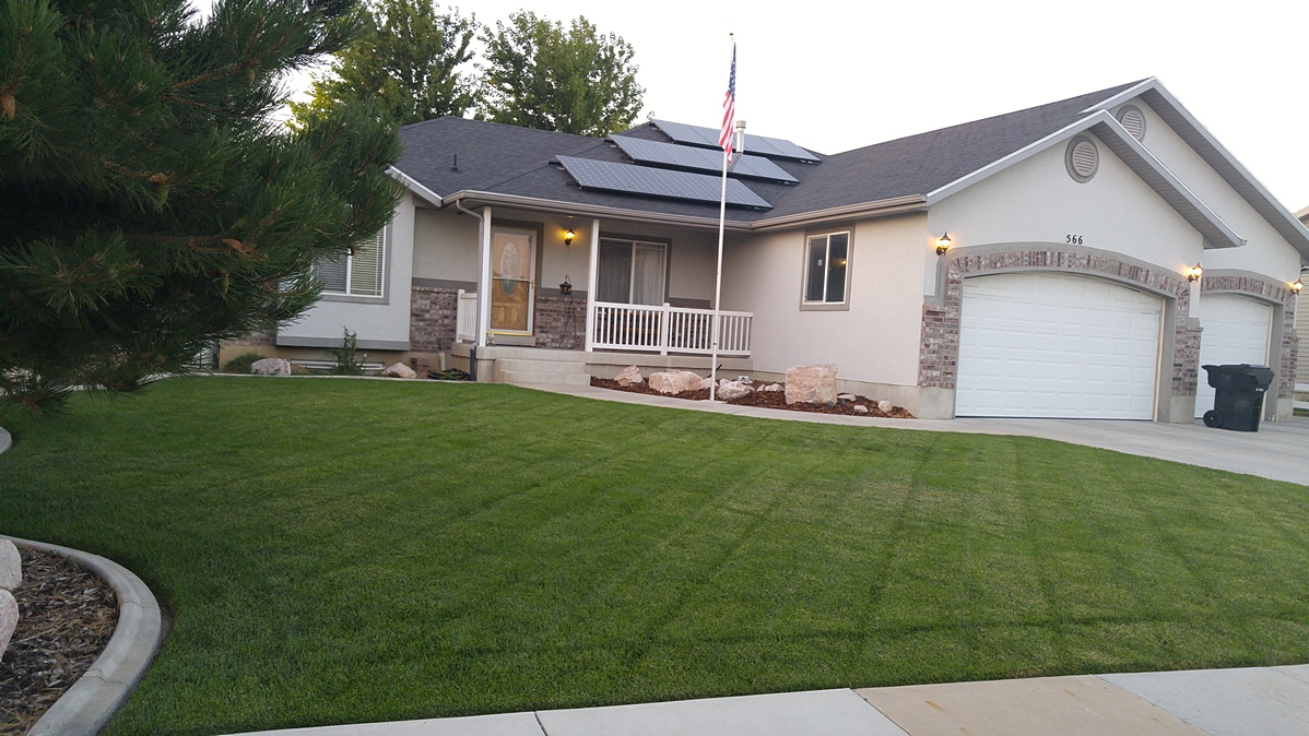
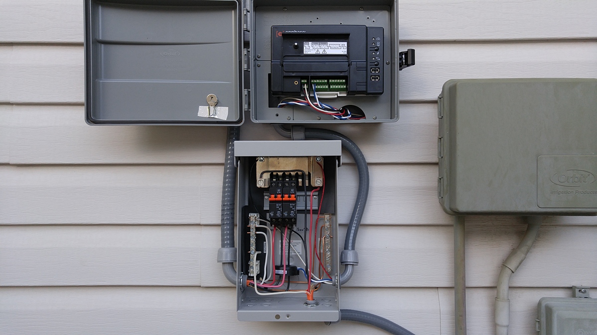
Scotty B 6.6kW Grid-Tied Roof Mount
Project Description
Canadian Solar CS6K-275M Quartech Solar Panels, Enphase S280-60-LL-2-US Microinverters and Envoy-S ENV-S-AM1-120 M Metered Communications Gateway, IronRidge XR-100 Rails with 29-70TB Mid Clamps, 29-7000 End Clamps and RF-FLSH-001B FlashFeet, MidNite Solar MNPV6-AC Disconnect Micro Combiner.
Customer Comments
"We enjoyed putting it together and working with your professional staff. They caught several compatibility issues on our order and contacted us for clarification and adjustments that saved us time and money."
Project Photos


Project Components
| Qty | Item # | Description | |
| 24 | 1110-288 | Canadian Solar CS6K-275M Quartech Solar Panel | |
| 24 | 1430-219 | Enphase S280-60-LL-2-US Microinverter | |
| 1 | 2140-051 |  | Enphase Envoy-S ENV-S-AM1-120 M Metered Communications Gateway |
| 4 | 1340-784 | IronRidge XR-100-SPLC Splice Kit | |
| 4 | 1340-209 |  | IronRidge 29-4000-077 Wire Clip |
| 20 | 1340-787 |  | IronRidge XR-100-CAP End Cap |
| 24 | 1340-220 |  | IronRidge 29-5003-005 Enphase or SolarEdge Mounting Kit ** Clearance Item - All Sales Final ** |
| 2 | 1410-023 |  | Enphase ET-TERM-01 Branch Terminator |
| 1 | 1940-030 |  | MidNite Solar MNPV6-AC Disconnect Micro Combiner |
| 12 | 1410-026 |  | Enphase ET10-240-BULK Engage AC Trunk Cable |
| 12 | 1410-025 |  | Enphase ET17-240-BULK Engage AC Trunk Cable |
| 8 | 1340-775 |  | IronRidge XR-100-132B Rail |
| 7 | 1330-770 | IronRidge RF-FLSH-001B Flashfoot | |
| 5 | 1340-007 | IronRidge 29-7000-157B End Clamp | |
| 10 | 1340-215 |  | IronRidge 29-70TB-101B Mid Clamp ** Clearance Item - All Sales Final ** |
| 6 | 1340-777 |  | IronRidge XR-100-168B Rail |
Keith H 7.28kW Grid-Tied Roof Mount
Project Description
Suniva OPT280-60-4-1B0 Solar Panels, SolarEdge SE7600A-US-U Inverter with P300-5NA4ARS Optimizers and SE1000-ZBGW-K-NA Wireless ZigBee Kit, S-5! VB-47 Face-Fastened Roof Brackets, IronRidge XR-100 Rails with RS-GD-MCL-225B Grounding Mid Clamps and 29-7000-224B End Clamps.
Customer Comments
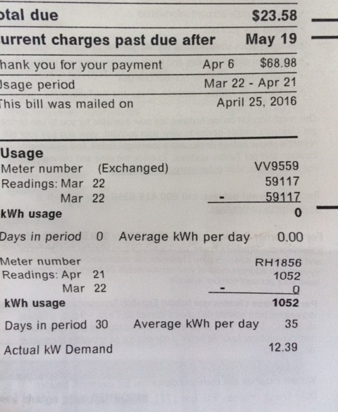
"I got my first full month power bill today. Check it out. Zero power purchased from the energy company."
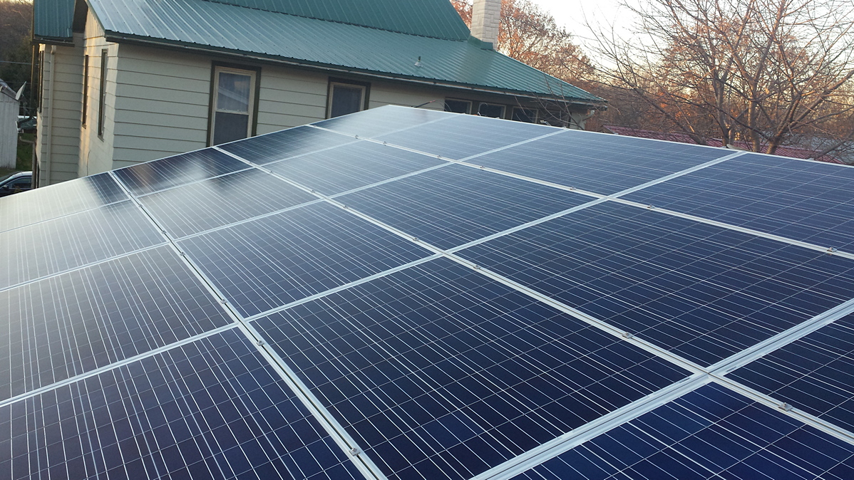
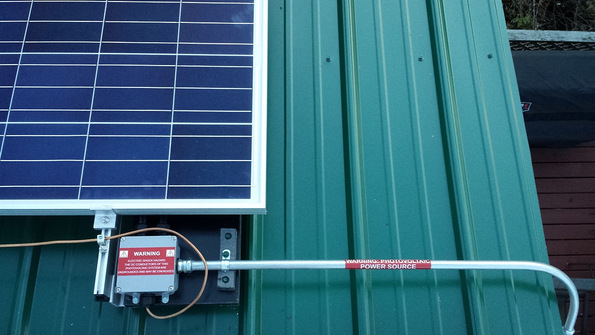
Project Photos
Project Components
| Qty | Item # | Description | |
| 26 | 1120-119 | Suniva OPT280-60-4-1B0-PT Solar Panel Pallet | |
| 1 | 1430-186 | SolarEdge SE7600A-US-U Inverter | |
| 26 | 1460-018 | Solaredge P300-5NA4ARS Optimizer | |
| 1 | 1450-117 |  | SolarEdge SE1000-ZBGW-K-NA Wireless ZigBee Kit |
| 2 | 2010-085 |  | 100' H4 PV Wire |
| 32 | 1330-171 |  | S-5! VB-47 Face-Fastened Roof System |
| 16 | 1340-774 |  | IronRidge XR-100-132A Rail |
| 12 | 1340-674 |  | IronRidge RS-GD-MCL-225B Grounding Mid Clamp ** Clearance Item - All Sales Final ** |
| 2 | 1340-007 | IronRidge 29-7000-224B End Clamp | |
| 8 | 1330-789 | IronRidge RS-LFT-001 Slotted L-Foot Kit | |
| 12 | 1340-784 | IronRidge XR-100-SPLC Splice Kit | |
| 3 | 1340-209 | | IronRidge 29-4000-077 Wire Clip |
| 1 | 1340-787 | | IronRidge XR-100-CAP End Cap |
| 3 | 2040-029 | IronRidge RS-GDST-001 Grounding Strap | |
| 13 | 1340-220 | | IronRidge 29-5003-005 Enphase or SolarEdge Mounting Kit ** Clearance Item - All Sales Final ** |
| 1 | 2040-026 | IronRidge RS-GDLG-002 Grounding Lug | |
| 1 | 1940-020 |  | Square D DU222RB AC Disconnect |
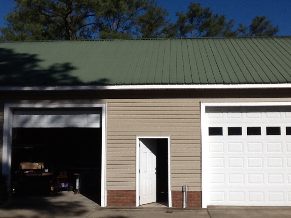
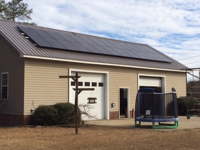
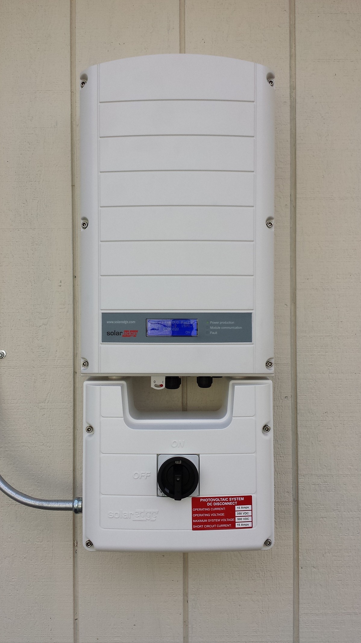
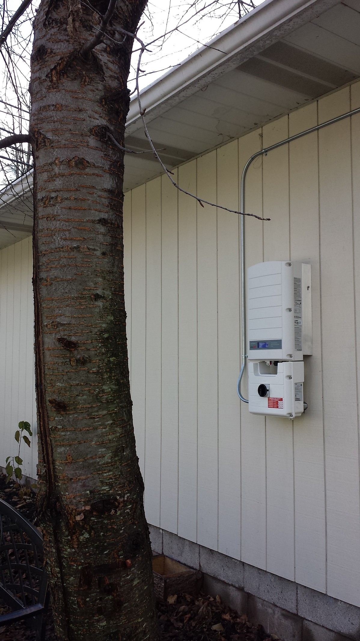
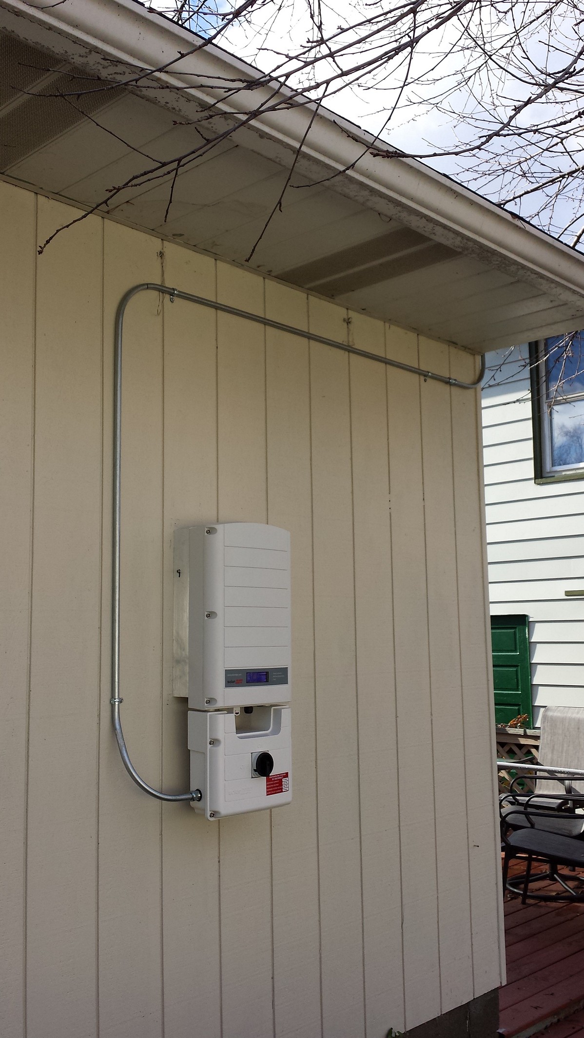
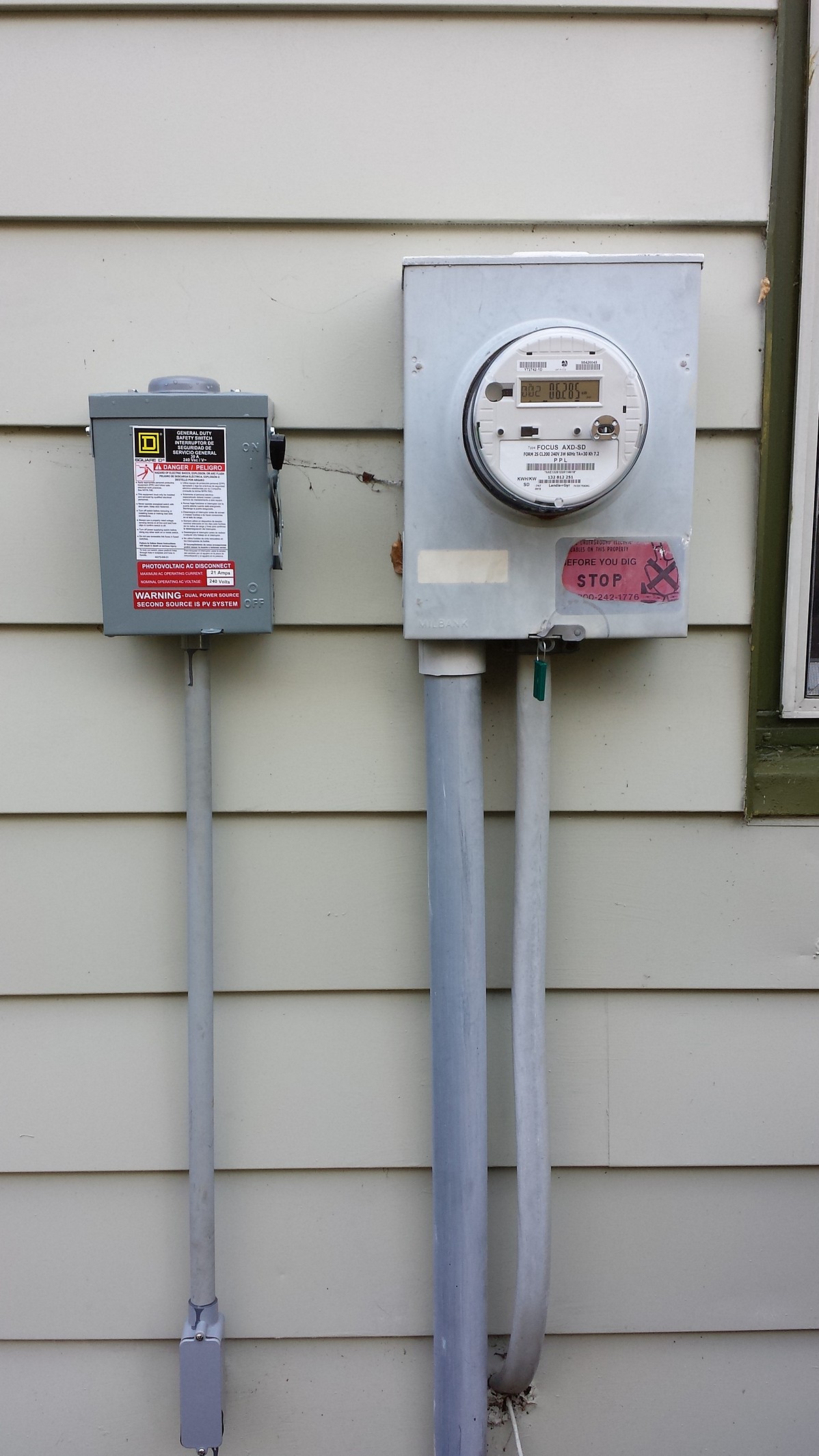
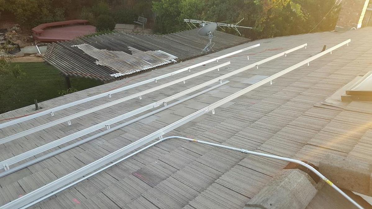
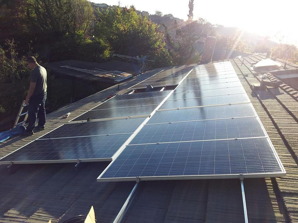
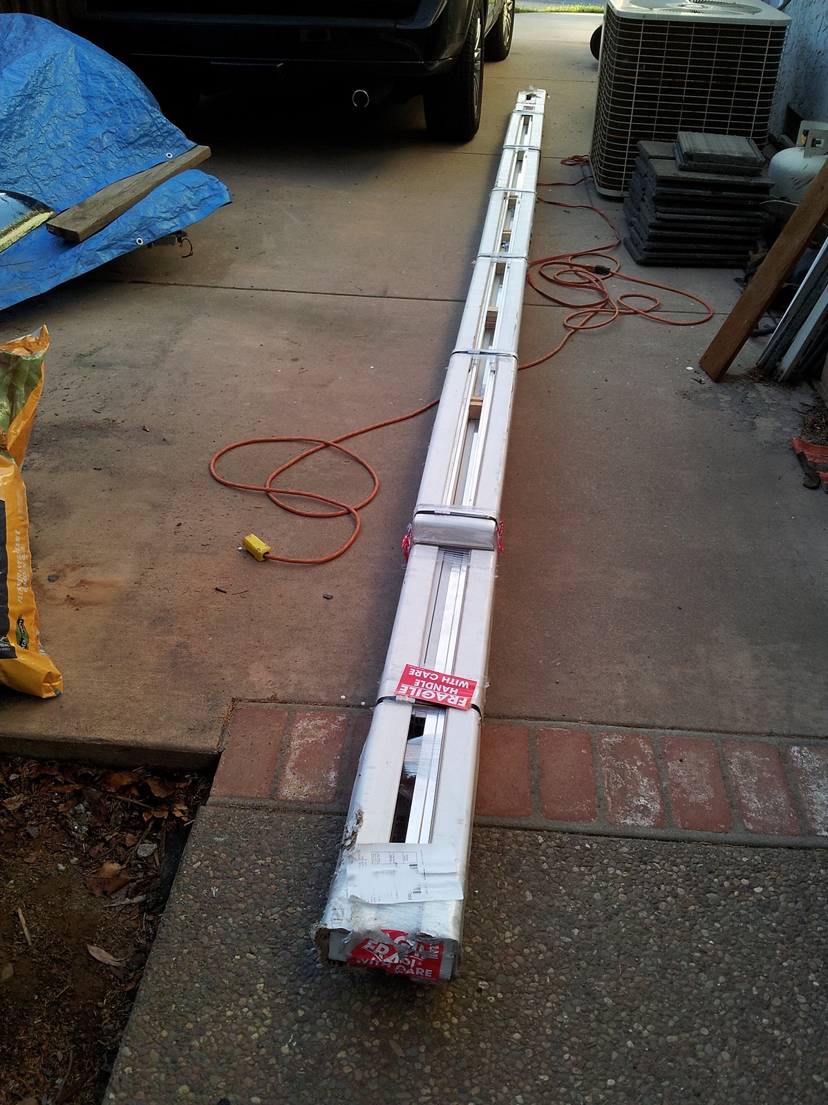
Raymond R 5.4kW Grid-Tied Roof Mount
Project Description
Axitec AC-270P/156-60S Solar Panels, SolarEdge SE5000A-US-U Inverter and P300-5NA4ARS Optimizers, IronRidge XR-100 Rails with RS-GD-MCL-225 Grounding Mid Clamps and 29-7000-157 End Clamps and RS-LFT-001 Slotted L-Feet, S-5! CorruBracket Mounts, Square D DU221RB AC Disconnect.
Customer Comments
"I would also like to thank you guys for all the support. The project is complete, connected to the grid and producing. Thanks again!"
Project Photos
Project Components


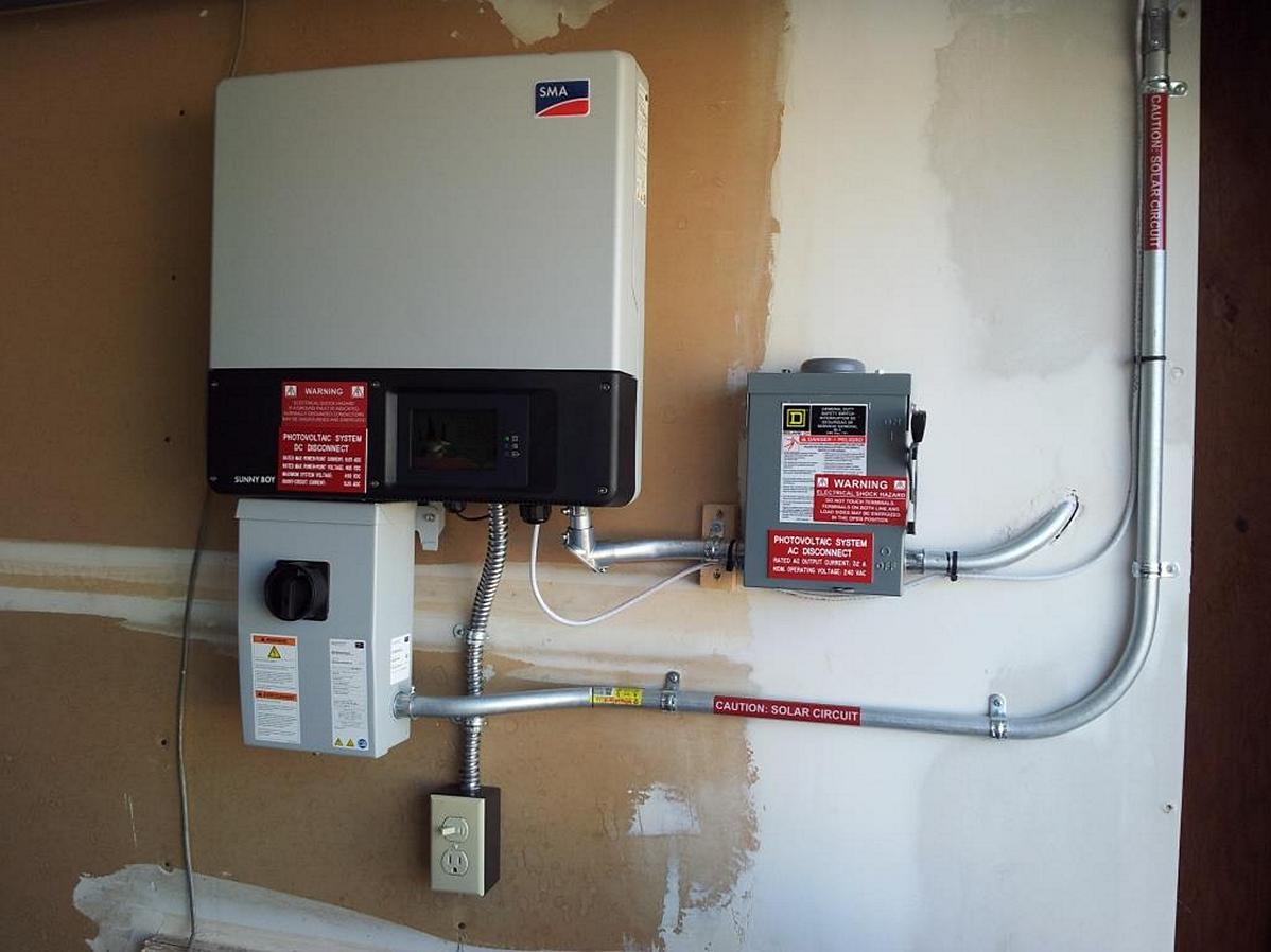
Gary M 8.32kW Grid-Tied Roof Mount
Project Description
Canadian Solar CS6X-320P Solar Panels, SMA Sunny Boy 7700TL-US-22 Inverter and SMA SWDM-US-10 Webconnect Interface Data Module, Unirac Rails, Quick Hook QMFTH Flat Tile Mounts, Wiley Electronics ACC-R4 and WEEB-ACC-PV Cable Clips.
Customer Comments
"This was a DYI project that saved us over 50% of the cost compared to the bids I received. I reviewed many installation videos on YouTube and decided I could do this myself and save significantly. To gain some hands on knowledge signed up to be a volunteer at SunWork which is a nonprofit San Francisco bay area company that does solar installations using volunteer help on weekends. After doing a couple volunteer installations I met some new friends and gained the confidence to do my own. I really appreciate the quick and accurate shipping from RES Supply along with completive pricing. Thanks for your helpful support."
Project Photos

Project Components


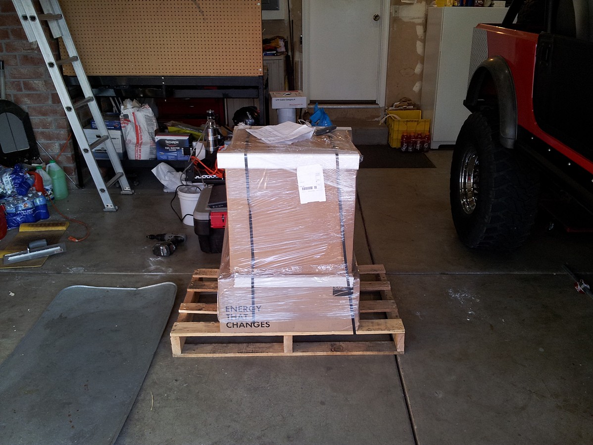
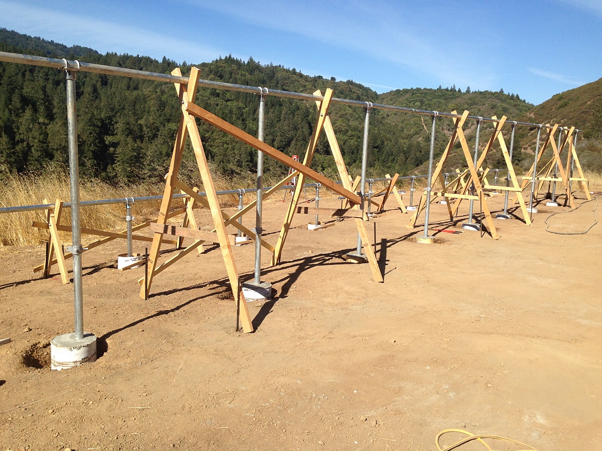
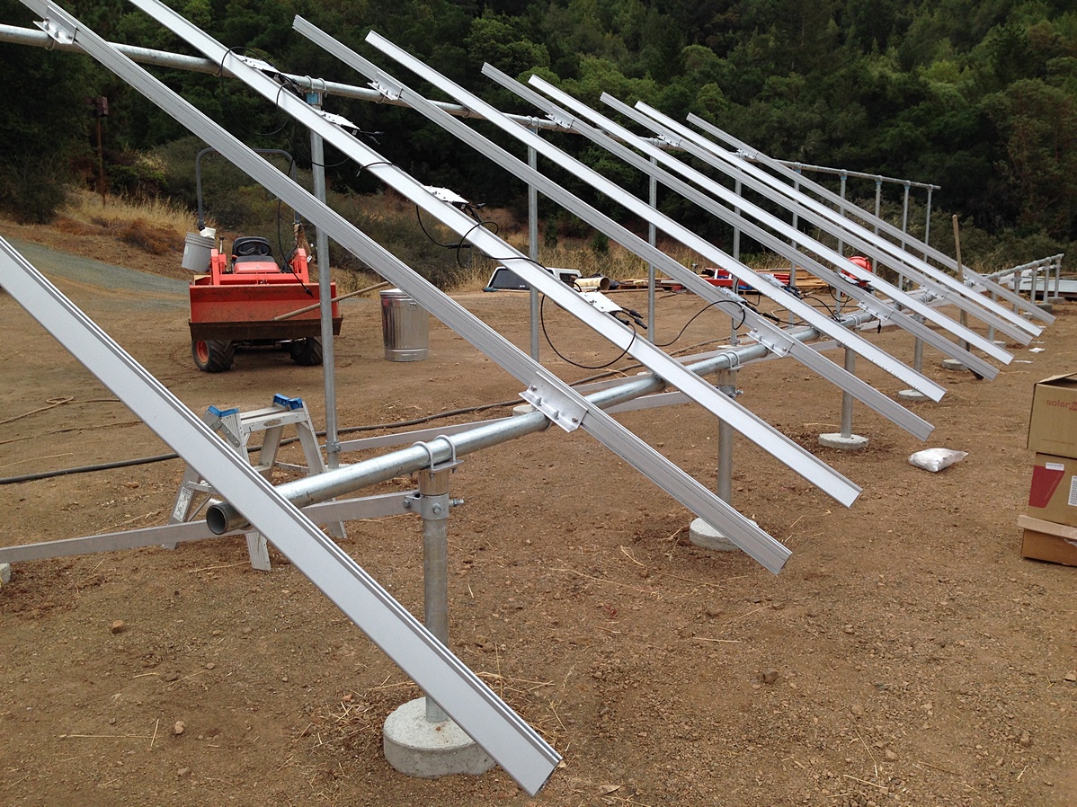
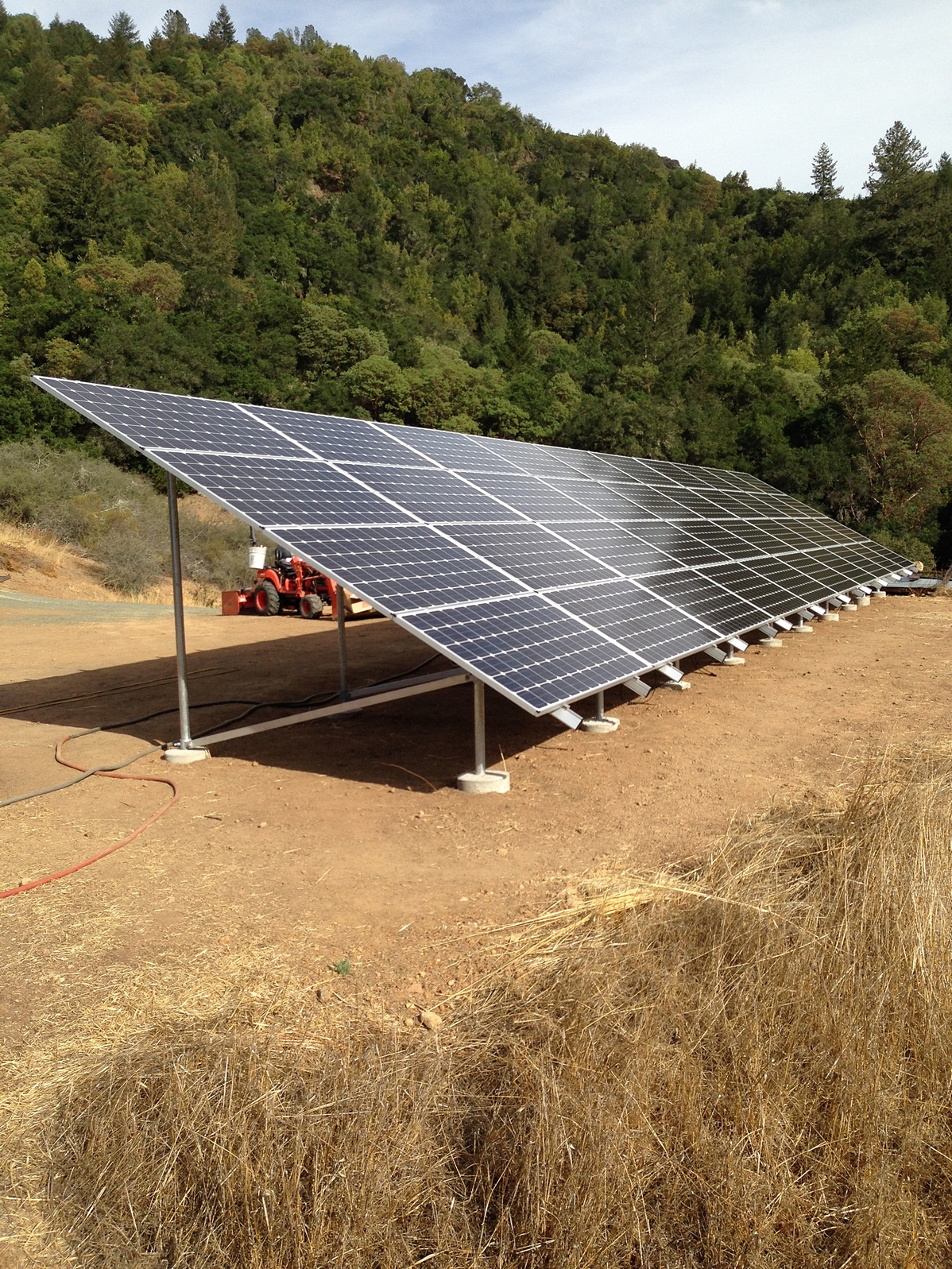
Roger P 12.8kW Grid-Tied Ground Mount
Project Description
SolarWorld SW340 XL Mono Solar Panels, SolarEdge SE11400A-US-U Inverter with P400-2NM4ARM Power Optimizers, IronRidge XR-1000 Rails with 70-0200-CBR Brace Assemblies, 70-0200-SGA Top Caps, 29-7001-001 SGA Rail Connectors, and 29-7000 Mid/End Clamps, OutBack FWPV-12 Combiner Box.
Customer Comments
"I did all the work myself. It has been a great experience working with RES."
Project Photos
Project Components
| Qty | Item # | Description | |
| 40 | 1120-116 | SolarWorld SW320 XL Mono 4.0-PT Solar Panel Pallet | |
| 1 | 1430-187 |  | SolarEdge SE11400A-US-U Inverter |
| 40 | 1460-016 | SolarEdge P400-2NM4ARM Power Optimizer | |
| 20 | 1310-702 |  | IronRidge 70-0200-SGA Top Cap |
| 10 | 1310-703 |  | IronRidge 70-0200-CBR Brace Assembly |
| 20 | 1340-772 |  | IronRidge XR-1000-168A Rail |
| 40 | 1310-054 | IronRidge 29-7001-001 SGA Rail Connector | |
| 15 | 1340-026 |  | IronRidge 29-7000-105 Mid Clamp ** Clearance Item - All Sales Final ** |
| 20 | 2040-022 |  | IronRidge 29-4000-002 WEEB Grounding Lug |
| 10 | 1340-827 | IronRidge 29-7000-130 End Clamp | |
| 6 | 1950-003 | Bussmann CHM1DU Touch-Safe Fuse Holder | |
| 6 | 2010-058 |  | Heyco M3234GBS-SM Strain Relief |
| 10 | 2040-002 |  | Amphenol HGLU-10 HelioLug |
| 3 | 2010-085 | | 100' H4 PV Wire |
| 1 | 1920-010 |  | OutBack FWPV-12 Combiner Box |
| 40 | 2040-023 |  | IronRidge 29-4000-001 WEEB DMC Compression Clip |
| 1 | 2040-027 |  | Wiley Electronics ACC-R4 Cable Clip |
| 8 | 1950-037 |  | Bussmann PV-20A10F Midget Fuse |
| 2 | Amphenol 18-H4TU0000 H4 Universal Unlocking Tool | ||
Solar Pool Heating Basics
Solar pool heating is the most cost-effective use of solar. Because water in pools is usually kept at about 80°F, the collectors are typically low-cost, low-temperature, unglazed panels made of polypropylene copolymers. UV inhibitors and antioxidants are integrated into the copolymer to make the panels resistant to ultraviolet rays and to oxidation due to pool chemicals & environmental factors. These have a much higher efficiency when they only need to heat large volumes of water a few degrees. Pool collectors will typically last from 12 to 20 years, more than two or three times the life of a gas heater, electric heater, or swimming pool heat pump.
The basic components of a solar pool system are solar pool collectors, automatic control, check/ ball valves, mounting kits, strap, and associated schedule 40 PVC pipes that are simply added to the existing pool pump, timer, and filter.
Solar pool panels are susceptible to ambient temperature and wind, which can cool the panels. To prolong the heat in the pool, a pool cover or blanket is recommended as well as a “no wind” location where the panels can absorb the most sun (southern exposure). The panels can be roof-mounted or ground mounted.
Wind Power Basics
“Do I have a good site for wind power?”
Wind-powered battery-charging systems can be cost-effective if the average wind speed is nine miles per hour or more at the location of the wind generator. If you are using wind in combination with photovoltaic power, it may be cost-effective if good wind is available only during part of the year. When the wind speed doubles, the power delivered is eight times as great. Most wind generators are designed to deliver maximum power at a wind speed of 30 mph. At 15 mph, they will deliver about 1/8 their rated power. The power output of a wind generator will decrease roughly 3% for every 1000 feet of elevation.
A wind generator should be mounted at least 20 feet higher than any obstruction within 300 feet to avoid turbulence. If you measure wind speed at ground level, you can expect about 1.5 times the wind speed 30 feet up, which equates to about three times the power. At 120 feet above the ground, wind speed will be twice what is measured at ground level and power output will be more than twice the output at 30 feet, and about 6 times the output at ground level.
Measuring Wind Speed
Before installing a wind-power generator, make a measurement for the wind-power resource at the site. Local weather data will be helpful, but wind is very site-specific based on local terrain, site elevation, wind direction, and any obstructions such as trees or buildings. Average wind speeds should be calculated, along with peak speeds during storm events.
Towers
Wind generators can be mounted on freestanding towers designed for antennas. They require a large, engineered concrete base for support, but since they do not require guy wires, they can be installed in a smaller space. Guyed steel truss towers, also designed for antenna mounting, are less costly and require a large area for guy wire placement. A tilt-up pole tower is the most economical and the easiest to install. Wiring and mounting of the wind generator are done before the tower is erected. No climbing is necessary. Steel tubing can be purchased locally to save freight.
Wind Electricity Glossary
-A-
Airfoil: The cross section profile of the leeward side of a wind generator blade. Designed to give low drag and good lift. Also found on an airplane wing.
Air gap: In a permanent magnet alternator, the distance between the magnets and the laminates.
Alternating current: Electricity that changes direction periodically. The period is measured in Cycles per Second (Hertz, Hz).
Alternator: A device that produces Alternating Current from the rotation of a shaft.
Amperage: A unit of electrical current, equal to Coulombs per second. This is the flow rate of electrons moving through a circuit, very roughly analogous to gallons per minute flowing from a faucet.
Ampere-hour: A measure of energy quantity, equal to amperes times hours. Also used to measure battery capacity.
Anemometer: A device that measures wind speed. Angle of attack: The angle of relative air flow to the blade chord.
Annealing: A heat treatment process that makes cold-rolled steel more suitable for forming and bending.
Area of a circle: Pi multiplied by the radius squared.
Armature: The moving part of an alternator, generator or motor. In many PM alternator designs, it carries the magnets and is attached to the blades and hub. Also called a rotor.
Axial alternator: An alternator design where a flat disc carrying magnets on the face (the Armature) rotates near a flat disc carrying coils (the Stator).
Axis: The centerline of a rotating object’s movement.
-B-
Balancing: With wind turbine blades, adjusting their weight and weight distribution through 2 axes so all blades are the same. unbalanced blades create damaging vibration.
Battery: An electrochemical device for storing energy.
Battery bank: An array of batteries connected in series, parallel, or both.
Bearing: A device that transfers a force to structural supports. In a wind generator, bearings allow the shaft to rotate freely, and allow the machine to yaw into and out of the wind.
Belt: A device for transferring power from a rotating shaft to a generator. Allows the use of pulleys to change the ratio of shaft speed to and from the generator.
Betz coefficient: 59.3%. This is the theoretical maximum efficiency at which a wind generator can operate, by slowing the wind down. If the wind generator slows the wind down too much, air piles up in front of the blades and is not used for extracting energy.
Blade: The part of a wind generator rotor that catches the wind.
Brake drum windmill: A home-built wind generator design by Hugh Piggott of Scotland.
Braking system: A device to slow a wind turbine’s shaft speed down to safe levels electrically or mechanically.
Bridge rectifier: An array of diodes used to convert Alternating Current to Direct Current. Single-phase bridge rectifiers use 4 diodes, 3 -phase bridge rectifiers use 6 diodes.
Brushes: Devices for transferring power to or from a rotating object. Usually made of carbon- graphite.
-C-
Ceramic magnets: See Ferrite Magnets.
Chord: The width of a wind turbine blade at a given location along the length.
Coercivity: The amount of power needed to magnetize or demagnetize a permanent magnet. Measured in MegaGauss Oersted (mGO)
Cogging: The cyclic physical resistance felt in some alternator designs from magnets passing the coils and gaps in the laminates. Detrimental to start-up.
Coil: A length of wire wound around a form in multiple turns.
Cold-rolled steel: Steel processed by working at room temperatures. More expensive than hot-rolled steel.
Commutator: The rotating part of a DC generator.
Concave: A surface curved like the interior of a circle or sphere.
Convex: A surface curved like the exterior of a circle or sphere.
Cowling: See Nacelle.
Current: See Amperage.
Cut-In: The rotational speed at which an alternator or generator starts pushing electricity hard enough (has a high enough voltage) to make electricity flow in a circuit.
Cyanoacrylate: A fast-setting, hard and brittle adhesive.
Cycles per second: Measured in Hertz. In electricity, it is the number of times an AC circuit reaches both minimum and maximum values in one second.
-D-
Darrieus: A Vertical Axis Wind Turbine design from the 1920’s and 1930’s by F.M. Darrieus, a French wind turbine designer.
DC: See Direct Current.
Delta: A 3-phase alternator wiring configuration in which all phases are connected in series.
Diameter: A straight line passing through the center of a circle, and ending on both edges. Equal to 2 times the radius.
Diode: A solid-state device that allows electricity to flow in only one direction.
Downwind: Refers to a Horizontal Axis Wind Turbine in which the hub and blades point away from the wind direction, the opposite of an upwind turbine.
Drag: In a wind generator, the force exerted on an object by moving air. Also refers to a type of wind generator or anemometer design that uses cups instead of a blades with air foils.
Dump load: A device to which wind generator power flows when the system batteries are too full to accept more power, usually an electric heating element. This diversion is per formed by a Shunt Regulator, and allows a load to be kept on the alternator or generator.
Duty cycle: In a circuit, the ratio of off time to on time.
Dynamo: A device that produces Direct Current from a rotating shaft. See Generator.
-E-
Eddy currents: Currents that flow in a substance from variations in magnetic induction. See also Lenz Effect. Laminates are used to prevent eddy currents, which cause physical and electrical resistance in an alternator or transformer, therefore wasting power.
Efficiency: The ratio of energy output to energy input in a device.
Electromagnet: A device made of wire coils that produces a magnetic field when electricity flows through the coils.
Epoxy: A 2-part adhesive system consisting of resin and hardener. It does not start to harden until the elements are mixed together. NOT compatible with Fiberglas® Resin.
Excitation: Using an electric current to create a magnetic field. See Electromagnet.
-F-
Fatigue: Stress that causes material failure from repeated, cyclic vibration or stress.
Ferrite magnets: Also called Ceramic Magnets. Made of Strontium Ferrite. High Coercivity and Curie Temperature, low cost, but brittle and 4- 5 times weaker than NdFeB magnets.
Fiberglas® resin: Another 2-part adhesive system, NOT compatible with epoxy. Of ten used for making castings, since it is much cheaper than epoxy.
Field: See Magnetic Field.
Flux: See Magnetic Field.
Freewheeling: A wind generator that is not connected to a load is freewheeling, and in danger of self- destruction from over speeding.
Frequency: See Cycles per Second.
Furling: The act of a wind generator yawing out of the wind either horizontally or vertically to protect itself from high wind speeds.
Furling tail: A wind generator protection mechanism where the rotor shaft axis is offset horizontally from the yaw axis, and the tail boom is both offset horizontally and hinged diagonally, thus allowing the tail to fold up and in during high winds. This causes the blades to turn out of the wind, protecting the machine.
-G-
Gauss: A unit of magnetic induction, equal to 1 Maxwell per square centimeter. Higher Gauss measurements mean more power can be induced to flow in an alternator. Gauss readings can be increased by putting steel behind magnets, stacking magnets, or using larger or higher-grade magnets.
Gearing: Using a mechanical system of gears or belts and pulleys to increase or decrease shaft speed. Power losses from friction are inherent in any gearing system.
Generator: A device that produces Direct Current from a rotating shaft.
Governor: A device that regulates the speed of a rotating shaft, either electrically or mechanically.
Guy anchor: Attaches tower guy wires securely to the earth.
Guy radius: The distance between a wind turbine tower and the guy anchors.
Guy wire: Attaches a tower to a guy anchor and the ground.
-H-
H-Rotor: A Vertical Axis Wind Turbine design. HAWT: See Horizontal Axis Wind Turbine. Hertz: Frequency measurement. See Cycles per Second.
Horizontal axis wind turbine: A “normal” wind turbine design, in which the shaft is parallel to the ground, and the blades are perpendicular to the ground.
Hub: The center of a wind generator rotor, which holds the blades in place and attaches to the shaft.
-I-
Impedance: See Resistance.
Induction: The production of a magnetic field by the proximity of a electric charge or the production of a magnetic field by proximity of an electric charge.
Induction motor: An AC motor in which the rotating armature has no electrical connections to it (ie no slip rings), and consists of alternating plates of aluminum and steel.
-K-
Kerf: The width of a cut made by a saw.
Kilowatt: 1000 Watts (see Watt).
kW: See Kilowatt.
-L-
Laminations: Electrical circuit core parts, found in motors, generators, alternators and transformers. When core parts are subjected to alternating electrical or magnetic fields, the buildup of eddy currents causes physical and electrical power loss. Laminations are made of thin strips of materials that make good temporary magnets and poor permanent magnets, and each strip is insulated electrically from the next.
Leading edge: The edge of a wind turbine blade that faces toward the direction of rotation.
Leeward: Away from the direction from which the wind blows.
Lenz effect: See also Eddy Currents. From H.F.E Lenz in 1833. Electromotive force is induced with variations in magnetic flux. It can be demonstrated physically in many different ways- -for example dragging a strong magnet over an aluminum or copper plate, or shorting the terminals of a PM alternator and rotating the shaft by hand. Laminates are used to reduce power losses from this effect.
Lift: The force exerted by moving air on asymmetrically-shaped wind generator blades at right angles to the direction of relative movement. Ideally,...
Micro-Hydro Power Basics
How much power can you generate with a hydroelectric turbine?
Micro-hydro turbines require water to be piped from a higher elevation to a lower elevation where the turbine is installed. This pipeline is called a “penstock” and the elevation difference is called the “static head”. The “dynamic head” is the static head adjusted for losses due to friction in the pipeline.
The amount of power produced depends on the dynamic head, the amount of water flow and the efficiency of the turbine generator combination. To get an idea of the potential power generation in watts, multiply the dynamic head in feet, times flow in gallons per minute, times 0.18, times turbine efficiency. Turbine efficiency ranges from 35% to 70%, with higher efficiency at higher heads. To get a rough idea, use 0.40 (representing 40%) as a multiplier for efficiency.
Dynamic Head (ft) x Flow (gpm) x 0.18 x Turbine Efficiency (use 0.40) = Output watts
Water flows greater than a single micro-hydro turbine can handle can be accommodated by using multiple turbines with a penstock manifold, or separate penstocks running to each unit.
Pipelines
A hydroelectric turbine uses the energy from the pressure at the end of a gravity-fed pipeline. This pressure, usually measured in pounds per square inch (psi), is directly related to the head: the vertical drop from the top of the pipeline, where the water enters the system, to the turbine located at the bottom of the pipeline. The pressure at the lowest point of a pipeline is equal to 0.433 times the head, (the vertical distance in feet).
Pressure is a determining factor in how much power is available and what type of pipe is required. Polyethylene pipe can be used for pressures up to 100 psi, PVC pipe is available with pressure ratings from 160 to 350 psi and steel pipe can withstand 1000 psi or more. Check with your local plumbing supplier for pipe ratings. Pipe diameter is very important. All pipelines will cause the water flowing in them to lose some energy to friction. The pipe must be large enough for the maximum quantity of water it will carry.
The pressure at the bottom of a pipeline when water is not flowing is called static pressure. When water is flowing through the outlet or nozzle of the hydroelectric turbine, the pressure at the outlet is the dynamic pressure or running head. If you install a gate valve on the pipeline just above the turbine and a pressure gauge on a "T" fitting just above the gate valve, you will read the static pressure on the gauge when the valve is closed and the dynamic pressure when the valve is opened. The maximum power that can be delivered by a pipeline will occur when the dynamic pressure is approximately 2/3 of the static pressure.
The actual flow rate of the water in a hydroelectric system is determined by the diameter of the nozzle. We will supply a turbine with the proper size nozzle for your site, depending on the head, flow, length and diameter of the pipe.
Nozzle selection
Power output of a hydroelectric generator is determined by the pressure of the water at the nozzle and the amount of water flowing out of the nozzle. The larger the nozzle, the greater the flow will be. The nozzle must also be sized small enough to keep your pipeline full and keep the speed of the water in the pipe below 5 feet per second. The nozzle selection table on the next page shows water flow through various size nozzles at given pressures. Use this table to determine what size nozzle and how many nozzles you need to accommodate the flow of water you have and to deliver the amount of power you need. A pressure gauge in the pipe feeding your turbine, installed before the shutoff valve, can help you check proper operation and diagnose problems. When the valve is shut off, the gauge will read the static pressure in pounds per square inch psi (head in feet x 0.433). When the valve is turned on the gauge will read a lower (dynamic) pressure.
The difference between these two pressures represents your loss to friction in the pipe. The greater the flow, the greater your loss will be. (See PVC pipe loss table below.)
Flow Through Nozzles
The table below shows the flow in gallons per minute (gpm) through various diameter nozzles at a range of heads from 5 feet to 400 feet. Use this table to choose what nozzle size to use and how many nozzles a turbine must have to give the required flow to use all of the water available in the system.
| Head | Flow in gpm through these nozzle diameters: | RPM for | |||||||||||
|---|---|---|---|---|---|---|---|---|---|---|---|---|---|
| feet | psi | >1/8" | 3/16" | 1/4" | 5/16" | 3/8" | 7/16" | 1/2" | 5/8" | 3/4" | 7/8" | 1.0" | 4" turbine |
| 5 | 2.2 | - | - | - | - | 6.18 | 8.4 | 11 | 17.1 | 24.7 | 33.6 | 43.9 | 460 |
| 10 | 4.3 | - | - | 3.88 | 6.05 | 8.75 | 11.6 | 15.6 | 24.2 | 35 | 47.6 | 62.1 | 650 |
| 15 | 6.5 | - | 2.68 | 4.76 | 7.4 | 10.7 | 14.6 | 19 | 29.7 | 42.8 | 58.2 | 76 | 800 |
| 20 | 8.7 | 1.37 | 3.09 | 5.49 | 8.56 | 12.4 | 16.8 | 22 | 34.3 | 49.4 | 67.3 | 87.8 | 925 |
| 30 | 13 | 1.68 | 3.78 | 6.72 | 10.5 | 15.1 | 20.6 | 26.9 | 42 | 60.5 | 82.4 | 107 | 1140 |
| 40 | 17.3 | 1.94 | 4.37 | 7.76 | 12.1 | 17.5 | 23.8 | 31.1 | 48.5 | 69.9 | 95.1 | 124 | 1310 |
| 50 | 21.7 | 2.17 | 4.88 | 8.68 | 13.6 | 19.5 | 26.6 | 34.7 | 54.3 | 78.1 | 106 | 139 | 1470 |
| 60 | 26 | 2.38 | 5.35 | 9.51 | 14.8 | 21.4 | 29.1 | 38 | 59.4 | 85.6 | 117 | 152 | 1600 |
| 80 | 34.6 | 2.75 | 6.18 | 11 | 17.1 | 24.7 | 33.6 | 43.9 | 68.6 | 98.8 | 135 | 176 | 1850 |
| 100 | 43.3 | 3.07 | 6.91 | 12.3 | 19.2 | 27.6 | 36.6 | 49.1 | 76.7 | 111 | 150 | 196 | 2070 |
| 120 | 52 | 3.36 | 7.56 | 13.4 | 21 | 30.3 | 41.2 | 53.8 | 84.1 | 121 | 165 | 215 | 2270 |
| 150 | 65 | 3.76 | 8.95 | 15 | 23.5 | 33.8 | 46 | 60.1 | 93.9 | 135 | 184 | 241 | 2540 |
| 200 | 86.6 | 4.34 | 9.77 | 17.4 | 27.1 | 39.1 | 53.2 | 69.4 | 109 | 156 | 213 | 278 | 2930 |
| 250 | 108 | 4.86 | 10.9 | 19.9 | 30.3 | 43.6 | 59.4 | 77.6 | 121 | 175 | 238 | 311 | 3270 |
| 300 | 130 | 5.32 | 12 | 21.3 | 33.2 | 47.8 | 65.1 | 85.1 | 133 | 191 | 261 | 340 | 3590 |
| 400 | 173 | 6.14 | 13.8 | 24.5 | 38.3 | 55.2 | 75.2 | 98.2 | 154 | 221 | 301 | 393 | 4140 |
PVC Pipe Loss Table
Use the table below to determine what pipe size is required to efficiently allow necessary flow for your power need. Once you know the required flow for your system (gpm), find the head loss for various pipe sizes. Multiply the head loss number by the length of the pipe divided by 100 and you will get the loss of head for that pipe size. The actual head minus the head loss will give you the effective dynamic head in the system.
| Pipe Friction Loss Table – Head Loss in Feet per 100 Feet of Schedule 40 PVC Pipe | |||||||||||||||||||||||
|---|---|---|---|---|---|---|---|---|---|---|---|---|---|---|---|---|---|---|---|---|---|---|---|
| Pipe Dia. | Flow (gallons per minute) | ||||||||||||||||||||||
| (Inches) | 1 | 2 | 3 | 4 | 5 | 7 | 10 | 15 | 20 | 25 | 30 | 40 | 50 | 60 | 70 | 80 | 100 | 150 | 200 | 250 | 300 | 400 | 500 |
| 1/2 | 2.08 | 4.16 | 8.7 | 14.8 | 23.5 | 43 | |||||||||||||||||
| 3/4 | 0.51 | 1.02 | 2.2 | 3.7 | 5.73 | 10.5 | 20.1 | 42.5 | |||||||||||||||
| 1 | 0.1 | 0.55 | 0.68 | 1.15 | 1.72 | 3.17 | 6.02 | 12.8 | 21.8 | 32.9 | 46.1 | ||||||||||||
| 1-1/4 | 0.03 | 0.14 | 0.19 | 0.31 | 0.44 | 0.81 | 1.55 | 3.28 | 5.59 | 8.45 | 11.9 | 22 | 30.5 | 45.6 | |||||||||
| 1-1/2 | 0.07 | 0.08 | 0.13 | 0.22 | 0.38 | 0.72 | 1.53 | 2.61 | 3.95 | 5.53 | 9.43 | 14.3 | 20 | 28.6 | 36.7 | ||||||||
| 2 | 0.03 | 0.05 | 0.07 | 0.11 | 0.21 | 0.45 | 0.76 | 1.15 | 1.62 | 2.75 | 4.16 | 5.84 | 7.76 | 9.94 | 15.1 | 34.8 | 59.3 | ||||||
| 2-1/2 | 0.03 | 0.04 | 0.05 | 0.09 | 0.19 | 0.32 | 0.49 | 0.68 | 1.16 | 1.75 | 2.46 | 3.27 | 4.19 | 6.33 | 13.4 | 25.0 | 37.8 | 46.1 | |||||
| 3 | 0.02 | 0.03 | 0.07 | 0.11 | 0.17 | 0.23 | 0.4 | 0.6 | 0.85 | 1.13 | 1.44 | 2.18 | 4.63 | 7.88 | 11.9 | 18.4 | 40.1 | ||||||
| 4 | 0.04 | 0.06 | 0.11 | 0.16 | 0.22 | 0.3 | 0.38 | 0.58 | 1.22 | 2.08 | 3.15 | 4.41 | 7.52 | ||||||||||
| 5 | 0.03 | 0.04 | 0.05 | 0.07 | 0.1 | 0.13 | 0.19 | 0.4 | 0.69 | 1.05 | 1.46 | 2.49 | 3.76 | ||||||||||
| 6 | 0.02 | 0.03 | 0.04 | 0.05 | 0.08 | 0.16 | 0.28 | 0.43 | 0.6 | 1.01 | 1.53 | ||||||||||||
Solar Thermal Glossary
-A-
Absorber: The blackened surface in a collector that absorbs the solar radiation and converts it to heat energy.
Absorptance: The ratio of solar energy absorbed by a surface relative to the solar energy striking it. Solar collectors have high absorptive coatings.
Active System: A solar water heating system that requires external mechanical power e.g. pumps, collectors to move the collected heat.
Air System: Solar domestic hot water systems employing air-type collectors are available. Hot air generated by these collectors is fan forced through an air-to-liquid heat exchanger with the potable water being pumped through the liquid section of the exchanger. The heated water is then circulated through the storage tank in a similar fashion to the liquid collector system. Air does not need to be protected from freezing or boiling, is non-corrosive, and is free. However, air ducts and air handling units require greater space than piping, and air leaks are difficult to detect.
Altitude: The angular distance from the horizon to the sun.
Ambient Temperature: The temperature of the surrounding air.
ASHRAE: Abbreviation for the American Society of Heating and Air-Conditioning Engineers.
Auxiliary Heat: The extra heat provided by a conventional heating system for periods of cloudiness or intense cold when a solar heating system cannot provide enough.
Azimuth: The angular distance between true south and the point on the horizon directly below the sun.
-B-
British Thermal Unit (BTU): The quantity of heat needed to raise the temperature of one pound of water one degree Fahrenheit.
-C-
Calorie: The quantity of heat needed to raise the temperature of one gram of water one degree Celsius.
Closed-Loop System: A solar system where the transfer fluid does not mix with the potable water and uses a heat exchanger to heat the household water by conduction and/or convection.
Coefficient of Heat Transmission: The rate of heat loss in BTU per hour through a square foot wall or other building surface when the difference between indoor and outdoor air temperatures is one degree Fahrenheit.
Collector (Solar): A device that collects solar radiation and converts it to heat. A solar hot water collector is usually an insulated box, with a tempered, low iron glass cover. Solar pool collectors usually do not have insulation or a cover plate.
Collector Efficiency: The ratio of usable heat energy extracted from a collector to the solar energy striking the cover.
Concentrating Collector: A device which concentrates the sun’s rays on an absorber surface which is significantly smaller than the overall collector area.
Conductance: The rate of heat flow (in BTUs per hour) through an object when a 1° F. Temperature difference is maintained between the sides of the object.
Conduction: The flow of heat due to temperature variations within a material.
Conductivity: A measure of the ability of a material to permit conduction of heat flow through it.
Convection: The motion of fluid such as gas or liquid by which heat
Cover Plate: A sheet of glass or transparent plastic placed above the absorber in a flat plate collector.
-D-
Degree Day - DD: A unit that represents a 1 degree F. deviation from some fixed reference point (usually 65°F.) in the mean daily outdoor temperature. The colder it gets, the more DD available. Degree-day figures quantify how hot or cold the weather has been as a single index number for the region and month (or week). They allow you to account properly for the effect of weather on energy consumption.
Design Heat Load: The total heat loss from a house under the most severe winter conditions likely to occur.
Design Temperature: The temperature close to the lowest expected for a location, used to determine the design heat load.
DHW: Domestic Hot Water
Diffuse Radiation: Indirect sunlight that is scattered from air molecules, dust and water vapor.
Direct Radiation: Solar radiation that comes straight from the sun, casting shadows on a clear day.
Drain Down System: Potable water is circulated from the storage tank through the collector loop. Freeze protection is provided by solenoid valves opening and dumping the water at a preset low temperature. Collectors and piping must be pitched so that the system can drain down, and must be assembled carefully to withstand 100 psi city water line pressures. Pressure reducing valves are recommended when city water pressure is greater than the working pressure of the system.
Drain Back System: The solar heat transfer fluid automatically drains into a tank by gravity. Drain back systems are available in one or two tank configurations. A heat exchanger is necessary, because the city inlet pressure would prevent draining. The heat transfer fluid in the collector loop may be distilled or city water if the loop plumbing is copper. If the plumbing is threaded galvanized pipe, inhibitors may be added to prevent corrosion. Most inhibitors are non-potable and require a double wall heat exchanger. The pump used must be sized to overcome static head.
-E-
Emittance: A measure of the propensity of a material to emit thermal radiation.
Expansion Tank: A tank in a heating system that provides space for the physical expansion of water or a water solution.
-F-
Flat Plate Collector: A solar collection device in which sunlight is converted into heat on a plane surface without the aid of reflecting surfaces to concentrate the rays. It is the most efficient type of collector for use with temperatures between the freezing and boiling points of water and up to about 350 degrees F. when used with air as the working medium. Flat plate collectors are normally used with the flat surface facing south and tilted to an angle appropriate to the intended use.
Forced Convection: The transfer of heat by the flow of fluids (such as air or water) driven by fans, blowers or pumps.
-G-
Galvanic Corrosion: A condition caused as a result of a conducting liquid making contact with two different metal which are not properly isolated physically and/or electrically.
Getters: A column or cartridge containing an active metal which will be sacrificed to protect some other metal in the system against galvanic corrosion.
Glaubers Salt: Sodium sulfate a eutectic salt that melts at 90°F. and absorbs about 104 Btu per pound as it does so.
Gravity Convection: The natural movement of heat that occurs when a warm fluid rises and a cool fluid sinks under the influence of gravity.
-H-
Header: The pipe that runs across the edge of an array of solar collectors, gathering or distributing the heat transfer fluid from, or to the risers in the individual collectors. This insures that equal flow rates and pressure are maintained.
Heat Capacity: A property of a material denoting its ability to absorb heat.
Heat Exchanger: A device, such as a coiled copper tube immersed in a tank of water, that is used to transfer heat from one fluid to another through a separating wall.
Heat Storage: A device or medium that absorbs collected solar heat and stores it for use during periods of inclement or cold weather.
Heat Storage Capacity: The amount of heat that can be stored by a material.
Heating Season: The period from early fall to late spring (in the northern hemisphere) during which additional heat is needed to keep a house comfortable for its occupants.
Heat Pump: A mechanical device that transfers heat from one medium to another, thereby cooling the first and warming the second.
Heat Sink: A medium or container to which heat flows.
Heat Source: A medium or container from which heat flows.
HTF: Heat Transfer Fluid used in closed loop systems e.g. glycol/water mixtures or pure water.
Hybrid Solar Energy System: A system that uses both active and passive methods in its operation.
-I-
ICS: Integrate Collector and Storage for solar water heater.
Indirect System: A solar heating or cooling system in which the solar heat is collected exterior to the building and transferred inside using ducts or piping and, usually fans or ducts.
Infrared Radiation: Electromagnetic radiation from the sun that has wavelengths slightly longer than visible light.
Insolation: The total amount of solar radiation direct, diffused and reflected-striking a surface exposed to the sky.
Insulation: A material with high resistance (R-value) to heat flow.
-K-
Kilowatt-hour (KWH): a unit of energy equal to 1 kilowatt (1,000 watts) of electric power being used for 1 hour. Equivalent to 3,413 BTU’s of thermal energy or 1 1/3 hp of mechanical energy.
-L-
Langley: A measure of solar radiation; equal to one calorie per square centimeter.
-M-
Murphy’s Law: Anything that can go wrong will go wrong at the worst possible way when you least expect it.
-N-
NABCEP: North American Board of Certified Energy Practitioners
NOAA – National Oceanic & Atmospheric Administration Worldwide Weather Data: Consult for lowest local freezes etc. on record, solar radiation data & local weather data.
Nocturnal Cooling: The cooling of a building or heat storage device by the radiation of excess heat into the night sky.
-O-
One-Tank Closed-Loop System: A conventional DHW tank, usually electrically heated, is converted to a solar DHW storage tank by installing an external heat exchanger coil. The lower electrical element is removed, leaving the uppermost of the usual two elements to provide auxiliary water heating and to achieve good stratification (layering of hotter water over progressively colder water).
Open Loop System: Some part of the System is open to the atmosphere, or system contains fresh or changeable water.
-P-
Passive System: A solar heating or cooling system that uses no external mechanical power e.g. pump or controller, to move the collected solar heat.
Percentage of Possible Sunshine: The percentage of daytime hours during which there is enough direct solar radiation to cast a shadow.
Potable Water:...