Solar Thermal Simplified
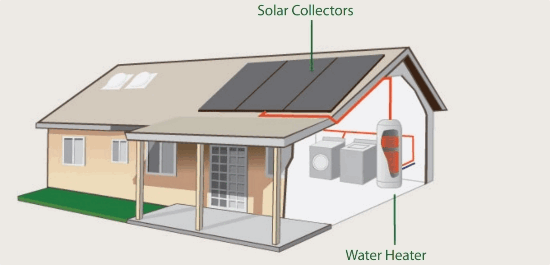
Solar Thermal uses radiation from the sun to produce heat energy. Solar Hot Water (SHW) systems use basic principles and components to capture incoming solar radiant energy and convert it to thermal energy by the collector. This thermal energy is then transferred to water (heating it) in a storage tank. SHW systems can operate in any climate, require little maintenance, use the free energy of the sun, and are cost effective. Performance factors include the solar energy input from the site, temperature, orientation, and tilt.
The major applications of solar thermal energy at present are heating water for domestic use (DHW), Radiant Floor Heating (RFH), space heating, and swimming pools. For these purposes, (with the exception of the pool), the general practice is to use flat-plate solar energy or evacuated tube collectors with a fixed southern orientation.
There are two main types of solar water heating systems:
Passive systems – Operate without the use of pumps or controls. Typical passive systems are Thermosiphon and Integrated Collector Storage (ICS). Some people favor passive solar systems because they offer a simple, low-cost system with no maintenance, no moving parts, and zero operational costs. The following should be considered for the installation of a passive thermal system: hot water load, hot water usage habits, the weight of the Thermosiphon tank, and the weight of the batch for the ICS system.
Active systems – Contain pumps and controls to regulate the flow and hot water production. Types of active systems include closed loop glycol, drainback, and open loop, all of which require freeze protection in areas that have any freezing temperatures.
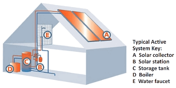
How Solar Hot Water Works
In the simplest solar thermal application, a discrete solar collector gathers solar radiation to heat air or water for domestic, commercial or industrial use. The solar domestic hot water system is designed to efficiently take full advantage of the sun’s radiant energy to heat water. The system is comprised of solar collectors and an automatic control unit that work together to create a reliable and carefree solar hot water heating system. The panel is usually a flat plate collector that consists of a metal box with a glass or plastic cover and a black absorber plate at the bottom and is usually mounted on a south-facing roof with a pitch.
Absorber plates are usually painted with selective coatings that absorb and retain heat better than ordinary black paint. They are normally made of metal, typically copper or aluminum, because they are good conductors of heat. Although copper is more expensive, it is a better conductor and is less prone to corrosion than aluminum. The sides and bottom of the collector are usually insulated to minimize heat loss.
There are different types of domestic solar hot water systems: active open loop, active closed loop, and unpressurized drainback systems. Closed loop hot water systems come in several variations and are slightly different than the open loop active systems as they utilize heat exchange solution. Used commonly in colder climates where freezing weather occurs, this FDA approved heat exchange solution, or food grade propylene glycol, works well in places where there are greater temperature differences. The closed loop hot water heater has the storage tank built in and directly connected to the solar collector panels, so that the solar energy collected is transferred directly to heat the water in the tank, and the tank itself uses no natural gas. A fully automated thermostat turns the booster switch on or off as needed to maintain the pre-set temperature. If the switch is on, it doesn’t mean you’re paying for supplementary electric or gas energy. Easy to operate, set the temperature desired, and the system does the rest.
Basic System Components of a Typical Active Pressurized or Closed Loop Glycol System:
|
|
|
|
|
|
|
|
|
|
|
|
Solar Electricity Glossary
-A-
Absorbed glass mat (AGM): A fibrous silica glass mat to suspend the electrolyte in batteries. This mat provides pockets that assist in the recombination of gasses generated during charging back into water.
Air mass: (Sometimes called air mass ratio) — Equal to the cosine of the zenith angle-that angle from directly overhead to a line intersecting the sun. The air mass is an indication of the length of the path solar radiation travels through the atmosphere. An air mass of 1.0 means the sun is directly overhead and the radiation travels through one atmosphere (thickness).
Alternating current (AC): Electric current in which the direction of flow is reversed at frequent intervals, usually 100 or 120 times per second (50 or 60 cycles per second or 50/60 Hz).
Altitude: The angle between the horizon (a horizontal plane) and the sun’s position in the sky. Measured in degrees.
Amorphous silicon: A non-crystalline semiconductor material that is of ten used in thin film photovoltaic modules.
Ampere (A) or amp: Unit for the electric current; the flow of electrons. One amp is 1 coulomb passing in one second. One amp is produced by an electric force of 1 volt acting across a resistance of 1 ohm. Sometimes this is abbreviated as I for intensity.
Ampere-hour (Ah): Quantity of electrical energy equal to the flow of one ampere of current for one hour. Typically used to quantify battery bank capacity.
Angle of incidence: Angle which references the sun’s radiation striking a surface. A “normal” angle of incidence refers to the sun striking a surface at a 90° angle.
Array: Any number of photovoltaic modules connected together to provide a single electrical output at a specified voltage. Arrays are of ten designed to produce significant amounts of electricity.
Avoided cost: The minimum amount an electric utility is required to pay an independent power producer, under the PURPA regulations of 1978, equal to the costs the utility calculates it avoids in not having to produce that power (usually substantially less than the retail price charged by the utility for power it sells to customers).
Azimuth: Angle between true south and the point directly below the location of the sun. Measured in degrees east or west of true south in northern latitudes.
-B-
Balance of system (BOS): All system components and costs other than the PV modules.
Battery: Two or more “cells” electrically connected for storing electrical energy. Common usage permits this designation to be applied also to a single cell used independently, as in a flashlight battery.
Battery capacity: The total number of ampere-hours that can be withdrawn from a fully charged cell or battery.
Battery cell: A galvanic cell for storage of electrical energy. This cell, after being discharged, may be restored to a fully charged condition by an electric current.
Battery cycle life: The number of cycles, to a specified depth of discharge, that a cell or battery can undergo before failing to meet its specified capacity or efficiency performance criteria.
Battery self-discharge: The rate at which a battery, without a load, will lose its charge.
Battery state of charge: Percentage of full charge or 100 percent minus the depth of discharge.
Blocking diode: A semiconductor device connected in series with a PV module and a storage battery to prevent a reverse current discharge of the battery through the module when there is no output, or low output from the cells. When connected in series to a PV string, it protects its modules from a reverse power flow preventing against the risk of thermal destruction of solar cells.
Bypass diode: A diode connected across one or more solar cells in a photovoltaic module such that the diode will conduct if the cell(s) become reverse biased. Alternatively, a diode connected anti -parallel across a part of the solar cells of a PV module. It protects these solar cells from thermal destruction in case of total or partial shading of individual solar cells while other cells are exposed to full light.
-C-
Cell: The basic unit of a photovoltaic module. This word is also commonly used to describe the basic unit of batteries (ie. a 6 -volt battery has (3) 2-volt cells).
Charge controller: A device that controls the charging rate and/or state of charge for batteries.
Charge rate: The current applied to a cell or battery to restore its available capacity.
Concentrator: A PV module that uses optical elements to increase the amount of sunlight incident on a PV cell. Concentrating arrays must track the sun and use only the direct sunlight because the diffuse portion cannot be focused onto the PV cells.
Conversion efficiency: The ratio of the electric energy produced by a photovoltaic device (under full sun conditions) to the energy from sunlight incident upon the cell.
Crystalline silicon: A type of PV cell made from a single crystal or polycrystalline slice of silicon.
Current: The flow of electric charge in a conductor between two points having a difference in potential (voltage).
Current at maximum power (Imp): The current at which maximum power is available from a module. [UL 1703]
Cycle life: Number of discharge-charge cycles that a battery can tolerate under specified conditions before it fails to meet specified criteria as to performance (e.g., capacity decreases to 80% of the nominal capacity).
-D-
Days of autonomy: The number of consecutive days a stand-alone system battery bank will meet a defined load without solar energy input.
DC to DC converter: Electronic circuit to convert DC voltages (e.g., PV module voltage) into other levels (e.g., load voltage). Can be part of a maximum power point tracker (MPPT).
Deep cycle battery: Type of battery that can be discharged to a large fraction of capacity many times without damaging the battery.
Demand Load: The total power required by a facility.
Depth of discharge (DOD): The amount of ampere hours removed from a fully charged cell or battery. Expressed as a percentage of rated capacity.
Diode: Electronic component that allows current flow in one direction only.
Direct current (DC): Electric current in which electrons flow in one direction only. Opposite of alternating current.
Discharge rate: The rate, usually expressed in amperes over time, at which electrical current is taken from the battery.
Disconnect: Switch gear used to connect or disconnect components of a PV system for safety or service.
Dual-axis tracking: A system capable of rotating independently about two axes and following the sun’s orientation and height in the sky (e.g., vertical and horizontal).
Duty cycle: The ratio of active time to total time. Used to describe the operating regime of appliances or loads.
-E-
Efficiency: The ratio of output power to input power. Expressed as a %.
Electric current: A flow of electricity.
Electrical grid: An integrated system of electricity distribution, usually covering a large area.
Electrolyte: A liquid conductor of electricity in which flow of current takes place by migration of ions. The electrolyte for a lead-acid storage cell is an aqueous solution of sulfuric acid.
Energy: The ability to do work. Stored energy becomes working energy when we use it.
Equalization: The process of mixing the electrolyte in batteries by periodically overcharging the batteries for a short period to “refresh” cell capacity.
-F-
Float life: Number of years a battery can keep its stated capacity when it is kept at float charge.
-G-
Gassing current: Portion of charge current that goes into electrolytical production of hydrogen and oxygen from the electrolytic liquid in the battery. This current increases with increasing voltage and temperature.
Gel-type battery: Lead-acid battery in which the electrolyte is composed of a silica gel matrix.
Gigawatt (GW): One billion watts. One million kilowatts. One thousand megawatts.
Grid-connected /Grid-Interaction /Grid-Tied: A PV system in which the PV array acts like a central generating plant, supplying power to the grid.
Grid-interactive: See ‘grid-connected (PV system).’
-H-
Hybrid system: A PV system that includes other sources of electricity generation, such as wind or fossil fuel generators.
-I-
Insolation: Sunlight, direct or diffuse. From incident solar radiation: usually expressed in watts per square meter. Not to be confused with ‘insulation’.
Interconnect: A conductor within a module or other means of connection which provides an electrical interconnection between the solar cells.
Inverters: Devices that convert DC electricity into AC electricity (single or multiphase). Either for stand-alone systems (not connected to the grid) or for utility-interactive systems.
I-V curve: A graphical presentation of the current versus the voltage from a photovoltaic device as the load is increased from the short circuit (no load) condition to the open circuit (maximum voltage) condition. Typically measured at 1,000 watts per square meter of solar insolation at a specific cell temperature. The shape of the curve characterizes cell performance.
-J-
Junction box: An electrical box designed to be a safe enclosure in which to make proper electrical connections. On PV modules, this is where PV strings are electrically connected.
-K-
Kilowatt (kW): 1,000 watts.
Kilowatt-hour (kWh): One thousand watt hours. The kWh is a unit of energy. 1 kWh = 3,600 kJ.
-L-
Life cycle cost: An estimate of the cost of owning and operating a system for the period of its useful life. Usually expressed in terms of the present value of all lifetime costs.
Load: Anything in an electrical circuit that, when the circuit is turned on, draws power from that circuit.
-M-
Maximum power point (MPP): The point on the current-voltage (I -V) curve of a module under illumination, where the product of current and voltage is maximum. For a...
PV System Final Installation Checklist
This section contains a system installation checklist that can be used as a final check for a newly installed system or as a maintenance assessment for an existing system. For additional reference material on system installation checklists, refer to NABCEP's "PV Installers Task Analysis" (available on their website: www.nabcep.org).
| Before Testing the System | |
| Use proper safety procedures and equipment when working with electricity. | |
| Verify that all disconnects are locked in the open position with a warning label. (This insures that power can not travel further down the line until properly tested, and warns others that there may be live conductors in the box). | |
| PV Array | |
| Make sure all modules are attached securely to their mounting brackets. | |
| Visually inspect the array for cracked modules, damaged junction boxes, and loose wires. | |
| Visually inspect that all module ‘quickconnects’ are tight. | |
| Open each combiner box and test open circuit voltage on each series string to verify correct voltage and polarity. Recheck torque on all DC terminals. | |
| Before powering up the system, at final array breakers, repeat open circuit voltage tests to verify correct voltage and polarity. | |
| Verify modules are wired so that they can be removed without interrupting the grounded conductor. | |
| Check for labels on the modules. NEC® 2005, Article 690.51: "Modules shall be marked with identification of terminals or leads as to polarity, maximum overcurrent device rating for protection, and with rated 1) open-circuit voltage, 2) operating voltage, 3) maximum permissible system voltage, 4) operating current, 5) short-circuit current, and 6) maximum power." See NEC® 2005, Article 690.52 for AC module requirements. | |
| Wiring | |
| Check exposed array wiring for correct rating and sunlight resistant insulation. | |
| Check that all wiring and conduit is appropriately rated, neat, and well supported. | |
| Check that strain reliefs/cable clamps are properly installed on all cables and cords by pulling on cables to verify (NEC® 2005, Article 300.4, and Article 400.10). | |
| Make sure that all grounded conductors are white and equipment grounding conductors are green or bare (NEC® 2005, Article 200.6(A)). | |
| Verify that the conductor rating of the PV circuit is at least 156% of the rated short circuit current (1250/0 X 1250/0 = 1560/0). | |
| Verify that all junction boxes are accessible. | |
| Overcurrent Protection | |
| Verify that the overcurrent device rating of the PV circuit is at least 156% of the rated short circuit current (125% X 1250/0 = 156%). | |
| Make sure DC voltage and current ratings are clearly marked on overcurrent protection. | |
| Charge Controllers | |
| Torque all terminations again. | |
| Check that all voltage settings are properly set for the appropriate battery type and proper voltage. | |
| If the system is connected to a utility interactive inverter, make sure that the settings of the charge controller(s) do not interfere with the proper operation and dispatch of the inverter system. | |
Verify that charge controller operation matches the programmed settings by forcing the system to the set points and making sure that the unit performs the proper control function. You should test the following points:
| |
| Disconnects | |
| Verify that the disconnects are still locked open and the warning label is still intact. | |
| Verify that there are means to disconnect and isolate all pieces of equipment in the system. | |
| If fuses are used, verify means to disconnect the power from both ends. | |
| Ensure switches are accessible and clearly labeled. | |
| Check the continuity of fuses and circuit breakers with power off. | |
| Check voltage drop across switches while operating. | |
| Check individual cell or battery voltages after equalization. | |
| Check the specific gravity of all questionable cells with a hydrometer. | |
| Batteries | |
| Store safety gear nearby (eye protection, rubber gloves, baking soda and distilled water). | |
| Retorque all battery connections. | |
| Coat each terminal with anticorrosive gel. | |
| Make sure that access to terminals is limited (NEC® 2005, Article 690.71(B)). | |
| Make sure that location provides adequate natural ventilation. Well-vented areas include garages, basements, and outbuildings, but not living areas. | |
| If battery contains flooded cells, top off cells with distilled water according to the manufacturers instructions. | |
| If battery contains flooded cells, be sure an eyewash station is accessible. | |
| Once inverter is operational, “equalize charge” the battery to ensure that the battery is properly connected and functioning correctly. | |
| Ideally, run the battery through a few heavy charge-discharge cycles to exercise the battery. | |
| Inverters in Grid-tied Systems | |
| While disconnects are open, retorque all electrical terminal connections on the inverter to tighten any connections that may have loosened since the initial installation. | |
| Verify in the inverter manual that the array open circuit voltage, under the record lowest temperature, is acceptable to the inverter. | |
| Check utility line voltage to verify that it is within the proper tolerances for inverter. If line voltage is above 124 volts AC before starting inverter, verify that the maximum voltage drop for the inverter output circuit is less than two volts. | |
| If the inverter measures and reports utility or inverter AC voltage on a display, verify that this voltage agrees with a measurement from a high quality, true-RMS AC volt meter. | |
| For non-battery-based inverters, once the inverter has started and is operational, check that the maximum power point tracking (MPPT) circuit is operating. This should be done during clear sky conditions if possible by monitoring array voltage from the open circuit condition until it reaches a point where system power peaks and then starts to drop again. Keep monitoring voltage until you note that the system voltage has been adjusted up and down several times. | |
| Verify that the operating voltage is near the expected peak power voltage for the conditions of the test, this can be found in most manufacturers literature. | |
| Properly connect the temperature compensation probe to control battery voltage. | |
| Follow inverter-starting procedure from the manufacturer’s manual. | |
| Instruct the homeowner on what to do in the event of an inverter-failure and provide them with an initial start-up test report. | |
| Inverters in Battery-based Systems | |
| While disconnects are open, retorque all electrical terminal connections on the inverter to tighten any connections that may have loosened since the initial installation. | |
| For battery-based inverters, use the programming features of the inverter to charge the battery, and then connect the battery to the DC source to ensure that these functions are operating properly. | |
| Follow inverter-starting procedure from the manufacturer’s manual./td | |
| Instruct the homeowner on what to do in the event of an inverter failure and provide them with an initial start-up test report. | |
| Grounding | |
| Verify that only one connection in the DC circuits and one connection in the AC circuits (grounded conductor to grounding conductor) is being used for system grounding referenced to the same point (NEC® 2005, Article 250.21). | |
| Check to see that equipment grounding conductors and system grounding conductors have as short a distance as possible to ground. | |
| Check that non-current carrying metal parts are grounded properly (array frames, racks, metal boxes, etc). | |
| Incorporate ground fault protection on systems required by the NEC®. Note: Terminal lugs bolted on an enclosure’s finished surface may be insulated because paint/finish at point of contact has not been properly removed. | |
| Check resistance of grounding system to earth ground. NEC® allows 25 ohms or less. | |
| Verify that the equipment grounding conductor is a green or bare wire and is properly sized. | |
| Safety Signs | |
| Label any fuse or circuit breaker that can be energized in either direction (NEC® 2005, Article 690.17). | |
| Post an “Interactive Point of Connection” sign for interactive PV systems (NEC® 2005, Article 690.54). | |
| Place a sign at the equipment service entrance that states the type and location of in-site optional standby power sources (NEC® 2005, Article 702.8). | |
| Post a “No Smoking” sign near the batteries. | |
| Place a sign at the point of PV system disconnect listing: operating current, operating voltage, maximum system voltage and short-circuit current (NEC® 2005, Article 690.53). | |
| Provide any additional documentation that would be helpful to the homeowner, inspector, or fire officials. | |
Source:...
Battery Sizing Exercise
Problem:
Use the table below to specify a battery bank for the following photovoltaic system. The occupants of a remote home near Ojai, California are designing a photovoltaic system to meet their 1,080 watt hours per day AC electrical load. They have decided on a 12-volt direct current system and feel they need two days of autonomy. The maximum depth of discharge they desire over that two-day period is 50 percent. The occupants have tentatively selected the Model A battery from XYZ Manufacturer, a 6-volt battery rated at 200 amp hours. The occupants will keep the battery(s) in a conditioned space that will be maintained at 77°F.

Solution:
- To start, de-rate for inverter efficiency by dividing the AC Average Daily Load (1,080 watts) by the standard inverter efficiency figure (90% or 0.9).
- Multiply the resulting Average Amp-Hours/Day (100) by the Days of Autonomy (2) and divide by the Discharge Limit or DOD (50% or 0.5) and divide again by the Battery Ah Capacity for the specified battery (200). The resulting figure is the number of batteries in parallel (2).
- Next determine the number of batteries needed to achieve the system voltage by dividing the DC System Voltage (12) by the Battery Voltage (6). Then multiply this number (2) by the number of batteries in parallel (2) to determine the Total Batteries needed (4).
Source: “PHOTOVOLTAICS - Design and Installation Manual” by Solar Energy International.
Solar Certification Training from Professional Solar InstallersWith 18 IREC-ISPQ Certified Solar Photovoltaic Trainers and 24 NABCEP Certified Solar PV Installers — more than any other solar training organization — Solar Energy International's experienced team is on the forefront of renewable energy education. If you are seeking online solar training or in-person lab training for the NABCEP Entry Level Exam or NABCEP Installer Certification, why not receive your education from a team of the most experienced solar installer professionals in the industry? Many SEI trainers have participated in the most notable solar installations within their communities stateside, and in the developing world.To start your solar training path today with Solar Energy International, click here. |  |
Battery Wiring Configuration
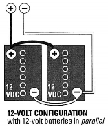
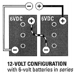
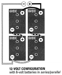
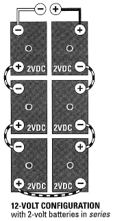
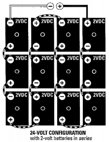
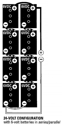
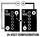
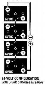
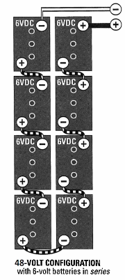
Batteries need to be configured to obtain the desired voltage and amp-hours. For instance, to achieve a 12V/400 Ah battery bank, you would do the following:
Two separate six-volt batteries rated at 200 Ah each are wired in series to obtain 12V direct current and 200 Ah. Two of these series strings are wired in parallel to achieve 12V direct current and 400 Ah.
The following figures show examples of wiring configurations for 12V, 24V and 48V battery banks, respectively.
Note: To create an equal path length for electron flow through the batteries, you must wire into opposite sides of the battery bank keeping the cables equal length.
|
|
|
|
12-Volt Battery Configurations | |||
|
|
|
|
24-Volt Battery Configurations | |||
Source: “PHOTOVOLTAICS - Design and Installation Manual” by Solar Energy International.
Solar Certification Training from Professional Solar InstallersWith 18 IREC-ISPQ Certified Solar Photovoltaic Trainers and 24 NABCEP Certified Solar PV Installers — more than any other solar training organization — Solar Energy International's experienced team is on the forefront of renewable energy education. If you are seeking online solar training or in-person lab training for the NABCEP Entry Level Exam or NABCEP Installer Certification, why not receive your education from a team of the most experienced solar installer professionals in the industry? Many SEI trainers have participated in the most notable solar installations within their communities stateside, and in the developing world.To start your solar training path today with Solar Energy International, click here. |  |
Maximum Ampacities for Wire
The table below displays approved ampacities of wires in conduit, raceway, cable or directly buried, based on an ambient temperature of 86°F (30°C). The NEC code allows rounding up cable ampacity to the next standard fuse or breaker size.
| Wire Size | Copper Conductor Temp. Rating | Aluminum Cond. Temp. Rating | ||
|---|---|---|---|---|
| 167°F (75°C) | 194°F (90°C) | 167°F (75°C) | 194°F (90°C) | |
| *14 | 20 | 25 | • | • |
| *12 | 25 | 30 | 20 | 25 |
| *10 | 35 | 40 | 30 | 35 |
| 8 | 50 | 55 | 40 | 45 |
| 6 | 65 | 75 | 50 | 60 |
| 4 | 85 | 95 | 65 | 75 |
| 2 | 115 | 130 | 90 | 100 |
| 1 | 130 | 150 | 100 | 115 |
| 1/0 | 150 | 170 | 120 | 135 |
| 2/0 | 175 | 195 | 135 | 150 |
| 3/0 | 200 | 225 | 155 | 175 |
| 4/0 | 230 | 260 | 180 | 205 |
* The overcurrent protection device may not exceed 30A for 10 AWG wire, 20A for 12 AWG wire and 15A for 14 AWG wire.
For ambient temperatures above 86°F (30°C), multiply the approved ampacities from the table above by the correction factor listed under the insulation temperature below.
| Temperature Range | 75°F Insulation | 90°F Insulation | |
|---|---|---|---|
| 31-35°C | 87-95 F | 0.94 | 0.96 |
| 36-40°C | 96-104 F | 0.88 | 0.91 |
| 41-45°C | 105-113 F | 0.82 | 0.87 |
| 46-50°C | 114-122 F | 0.75 | 0.82 |
| 51-55°C | 123-131 F | 0.67 | 0.76 |
| 56-60°C | 132-140 F | 0.58 | 0.71 |
Recommended Inverter Cable and Overcurrent Protection
The table below will help you choose your cable size and fuse or breaker size for a common inverter. Larger cables may be necessary if the distance from the inverter to the battery is greater than 10 feet (not recommended).
| Inverter Voltage | Continuous Watts | Max Inverter Input (Amps) | Fuse Size (Amps) | Circuit Breaker (Amps) | Wire Size (AWG) |
|---|---|---|---|---|---|
| 12-Volt | 600 | 80 | 80 | 80 | 2 |
| 800 | 107 | 110 | 110 | 2 | |
| 1000 | 134 | 200 | 175 | 2/0 | |
| 1500 | 200 | 300 | 250 | 4/0 | |
| 2400 | 320 | 400 | 250 | 4/0 | |
| 2500 | 334 | 400 | 250 | 4/0 | |
| 2800 | 382 | 400 | 250 | 4/0 | |
| 3000 | 400 | 400 | 250 | 4/0 | |
| 24-Volt | 600 | 40 | 50 | 50 | 8 |
| 800 | 54 | 75 | 75 | 4 | |
| 1000 | 67 | 80 | 100 | 2 | |
| 1500 | 100 | 110 | 110 | 2/0 | |
| 2400 | 160 | 200 | 175 | 2/0 | |
| 2500 | 167 | 200 | 175 | 2/0 | |
| 3000 | 200 | 300 | 250 | 4/0 | |
| 3500 | 230 | 300 | 250 | 4/0 | |
| 4000 | 265 | 300 | 250 | 4/0 | |
| 48-Volt | 3000 | 76 | 110 | 110 | 2/0 |
| 3600 | 90 | 110 | 110 | 2/0 | |
| 4000 | 148 | 200 | 175 | 2/0 | |
| 5500 | 185 | 400 | 250 | 4/0 |
Wire Loss Tables
The following tables list the maximum one-way wire distance for 12V, 24V, 28V and 120V systems with a 2% voltage drop. The first column lists the desired amperage and the other columns list the maximum length for each wire gauge.
12-Volt System - 2% Voltage Drop
| AMPS | #14 | #12 | #10 | #8 | #6 | #4 | #2 | 1/0 | 2/0 | 4/0 |
|---|---|---|---|---|---|---|---|---|---|---|
| 1 | 45 | 70 | 115 | 180 | 290 | 456 | 720 | • | • | • |
| 2 | 22.5 | 35 | 57.5 | 90 | 145 | 228 | 360 | 580 | 720 | 1060 |
| 4 | 10 | 17.5 | 27.5 | 45 | 72.5 | 114 | 180 | 290 | 360 | 580 |
| 6 | 7.5 | 12 | 17.5 | 30 | 47.5 | 75 | 120 | 193 | 243 | 380 |
| 8 | 5.5 | 8.5 | 15 | 22.5 | 35.5 | 57 | 90 | 145 | 180 | 290 |
| 10 | 4.5 | 7 | 12 | 18 | 28.5 | 45.5 | 72.5 | 115 | 145 | 230 |
| 15 | 3 | 4.5 | 7 | 12 | 19 | 30 | 48 | 76.5 | 96 | 150 |
| 20 | 2 | 3.5 | 5.5 | 9 | 14.5 | 22.5 | 36 | 57.5 | 72.5 | 116 |
| 25 | 1.8 | 2.8 | 4.5 | 7 | 11.5 | 18 | 29 | 46 | 58 | 92 |
| 30 | 1.5 | 2.3 | 3.5 | 6 | 9.5 | 15 | 24 | 38.5 | 48.5 | 77 |
| 40 | • | • | 2.8 | 4.5 | 7 | 11.5 | 18 | 29 | 36 | 56 |
| 50 | • | • | 2.3 | 3.6 | 5.5 | 9 | 14.5 | 23 | 29 | 46 |
| 100 | • | • | • | • | 2.9 | 4.6 | 7.2 | 11.5 | 14.5 | 23 |
| 150 | • | • | • | • | • | • | 4.8 | 7.7 | 9.7 | 15 |
| 200 | • | • | • | • | • | • | 3.6 | 5.8 | 7.3 | 11 |
24-Volt System - 2% Voltage Drop
| AMPS | #14 | #12 | #10 | #8 | #6 | #4 | #2 | 1/0 | 2/0 | 4/0 |
|---|---|---|---|---|---|---|---|---|---|---|
| 1 | 90 | 140 | 230 | 360 | 580 | 912 | 1440 | • | • | • |
| 2 | 45 | 70 | 115 | 180 | 290 | 456 | 720 | 1160 | 1440 | 2120 |
| 4 | 20 | 35 | 55 | 90 | 145 | 228 | 360 | 580 | 720 | 1160 |
| 6 | 15 | 24 | 35 | 60 | 95 | 150 | 240 | 386 | 486 | 760 |
| 8 | 11 | 17 | 24 | 45 | 71 | 114 | 180 | 290 | 360 | 580 |
| 10 | 9 | 14 | 17 | 36 | 57 | 91 | 145 | 230 | 290 | 460 |
| 15 | 6 | 9 | 14 | 24 | 38 | 60 | 96 | 153 | 192 | 300 |
| 20 | 4 | 7 | 9 | 18 | 29 | 45 | 72 | 115 | 145 | 232 |
| 25 | 3.6 | 5.6 | 7 | 14 | 23 | 36 | 58 | 92 | 116 | 184 |
| 30 | 3 | 4.8 | 5.6 | 12 | 19 | 30 | 48 | 77 | 97 | 154 |
| 40 | • | • | 4.8 | 9 | 14 | 23 | 36 | 58 | 72 | 112 |
| 50 | • | • | • | 7.2 | 11 | 18 | 29 | 46 | 58 | 92 |
| 100 | • | • | • | • | 5.8 | 9.2 | 14.4 | 23 | 29 | 46 |
| 150 | • | • | • | • | • | • | 9.6 | 15.4 | 19.4 | 30 |
| 200 | • | • | • | • | • | • | 7.2 | 11.6 | 14.6 | 22 |
48-Volt System - 2% Voltage Drop
| AMPS | #14 | #12 | #10 | #8 | #6 | #4 | #2 | 1/0 | 2/0 | 4/0 |
|---|---|---|---|---|---|---|---|---|---|---|
| 1 | 180 | 280 | 460 | 720 | 1160 | 1824 | 2880 | • | • | • |
| 2 | 90 | 140 | 230 | 360 | 580 | 912 | 1440 | 2320 | 2880 | 4240 |
| 4 | 40 | 70 | 110 | 180 | 290 | 456 | 720 | 1160 | 1440 | 2320 |
| 6 | 30 | 48 | 70 | 120 | 190 | 300 | 480 | 772 | 972 | 1520 |
| 8 | 22 | 34 | 60 | 90 | 142 | 228 | 360 | 580 | 720 | 1160 |
| 10 | 18 | 28 | 48 | 72 | 114 | 182 | 290 | 460 | 580 | 920 |
| 15 | 12 | 18 | 28 | 48 | 76 | 120 | 192 | 306 | 384 | 600 |
| 20 | 8 | 14 | 22 | 36 | 58 | 90 | 144 | 230 | 290 | 464 |
| 25 | 7.2 | 11.2 | 18 | 28 | 46 | 72 | 116 | 184 | 232 | 368 |
| 30 | 6 | 9.6 | 14 | 24 | 38 | 60 | 96 | 154 | 194 | 308 |
| 40 | • | • | 11.2 | 18 | 28 | 46 | 72 | 116 | 144 | 224 |
| 50 | • | • | 9.2 | 14.4 | 22 | 36 | 58 | 92 | 116 | 184 |
| 100 | • | • | • | • | 11.6 | 18.4 | 28.8 | 46 | 58 | 92 |
| 150 | • | • | • | • | • | • | 19.2 | 30.8 | 38.8 | 60 |
| 200 | • | • | • | • | • | • | 14.4 | 23.2 | 29.2 | 44 |
120-Volt System - 2% Voltage Drop
| AMPS | #14 | #12 | #10 | #8 | #6 | #4 | #2 | 1/0 | 2/0 | 4/0 |
|---|---|---|---|---|---|---|---|---|---|---|
| 1 | 450 | 700 | 1150 | 1800 | 2900 | 4560 | 7200 | • | • | • |
| 2 | 225 | 350 | 575 | 900 | 1450 | 2280 | 3600 | 5800 | 7200 | 10600 |
| 4 | 100 | 175 | 275 | 450 | 725 | 1140 | 1800 | 2900 | 3600 | 5800 |
| 6 | 75 | 120 | 175 | 300 | 475 | 750 | 1200 | 1930 | 2430 | 3800 |
| 8 | 55 | 85 | 150 | 225 | 355 | 570 | 900 | 1450 | 1800 | 2900 |
| 10 | 45 | 70 | 120 | 180 | 285 | 455 | 725 | 1150 | 1450 | 2300 |
| 15 | 30 | 45 | 70 | 120 | 190 | 300 | 480 | 765 | 960 | 1500 |
| 20 | 20 | 35 | 55 | 90 | 145 | 225 | 360 | 575 | 725 | 1160 |
| 25 | 18 | 28 | 45 | 70 | 115 | 180 | 290 | 460 | 580 | 920 |
| 30 | 15 | 24 | 35 | 60 | 95 | 150 | 240 | 385 | 485 | 770 |
| 40 | • | • | 28 | 45 | 70 | 115 | 180 | 290 | 360 | 560 |
| 50 | • | • | 23 | 36 | 55 | 90 | 145 | 230 | 290 | 460 |
| 100 | • | • | • | 18 | 29 | 46 | 72 | 115 | 145 | 230 |
| 150 | • | • | • | • | • | • | 48 | 77 | 97 | 150 |
| 200 | • | • | • | • | • | • | 36 | 58 | 73 | 110 |
Wire Sizing Chart and Formula
This chart is useful for finding the correct wire size for any voltage, length, or amperage flow in any AC or DC circuit. For most DC circuits, particularly between the PV modules and the batteries, we try to keep the voltage drop to 3% or less. There’s no sense using your expensive PV wattage to heat wires. You want that power in your batteries!
Note: This formula doesn’t directly yield a wire gauge size, but rather a “VDI” number, which is then compared to the nearest number in the VDI column, and then read across to the wire gauge size column.
1. Calculate the Voltage Drop Index (VDI) using the following formula:
VDI = AMPS x FEET ÷ (% VOLT DROP x VOLTAGE)
- Amps = Watts divided by volts
- Feet = One-way wire distance
- % Volt Drop = Percentage of voltage drop acceptable for this circuit (typically 2% to 5%)
2. Determine the appropriate wire size from the chart below.
- Take the VDI number you just calculated and find the nearest number in the VDI column, then read to the left for AWG wire gauge size.
- Be sure that your circuit amperage does not exceed the figure in the Ampacity column for that wire size. (This is not usually a problem in low-voltage circuits).
Example: Your PV array consisting of four 75W modules is 60 feet from your 12-volt battery. This is actual wiring distance, up pole mounts, around obstacles, etc. These modules are rated at 4.4 amps x 4 modules = 17.6 amps maximum. We’ll shoot for a 3% voltage drop. So our formula looks like:
| VDI = | 17.6 x 60 3[%] x 12[V] | = 29.3 |
Looking at our chart, a VDI of 29 means we’d better use #2 wire in copper, or #0 wire in aluminum. Hmmm. Pretty big wire. What if this system was 24-volt? The modules would be wired in series so each pair of modules would produce 4.4 amps. Two pairs x 4.4 amps = 8.8 amps max.
| Wire Size | Copper Wire | Aluminum Wire | ||
|---|---|---|---|---|
| AWG | VDI | Ampacity | VDI | Ampacity |
| 0000 | 99 | 260 | 62 | 205 |
| 000 | 78 | 225 | 49 | 175 |
| 00 | 62 | 195 | 39 | 150 |
| 0 | 49 | 170 | 31 | 135 |
| 2 | 31 | 130 | 20 | 100 |
| 4 | 20 | 95 | 12 | 75 |
| 6 | 12 | 75 | • | • |
| 8 | 8 | 55 | • | • |
| 10 | 5 | 30 | • | • |
| 12 | 3 | 20 | • | • |
| 14 | 2 | 15 | • | • |
| 16 | 1 | • | • | • |
Chart developed by John Davey and Windy Dankoff. Used with permission.
Source: “PHOTOVOLTAICS - Design and Installation Manual” by Solar Energy International.
Solar Certification Training from Professional Solar Installers
With 18 IREC-ISPQ Certified Solar Photovoltaic Trainers and 24 NABCEP Certified Solar PV Installers — more than any other solar training organization — Solar Energy International's experienced team is on the forefront of renewable energy education. If you are seeking online solar training or in-person lab training for the NABCEP Entry Level Exam or NABCEP Installer Certification, why not receive your education from a team of the most experienced solar installer professionals in the industry? Many SEI trainers have participated in the most notable solar installations within their communities stateside, and in the developing world.
To start your solar training path today with Solar Energy International, click here.
Disconnects
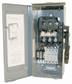
Each piece of equipment in a PV system, such as inverters, batteries, and charge controllers, must be able to be disconnected from all sources of power (NEC® 2005, Article 690.15). To comply with NEC® code, disconnects must satisfy the following items:
- They can be switches or circuit breakers.
- They need to be accessible.
- They must not have any exposed live parts.
- They must plainly indicate whether they are in the opened or closed position.
- They must be rated for the nominal system voltage and available current (NEC® 2005, Article 690.17).
Circuit breakers designed in the system for overcurrent protection can be used as disconnects. Fuses are not considered disconnects unless they are switched fuses.
The total number of disconnecting devices a PV system can have must be six or fewer switches or circuit breakers to shut off all sources of power (NEC® 2005, Article 690.14). These six disconnects must be grouped together and grouped with other disconnecting means for the system (NEC® 2005, Article 690. 14(C)(5)). Refer to NEC® for proper labeling.
Source: “PHOTOVOLTAICS - Design and Installation Manual” by Solar Energy International.
Solar Certification Training from Professional Solar Installers
With 18 IREC-ISPQ Certified Solar Photovoltaic Trainers and 24 NABCEP Certified Solar PV Installers — more than any other solar training organization — Solar Energy International's experienced team is on the forefront of renewable energy education. If you are seeking online solar training or in-person lab training for the NABCEP Entry Level Exam or NABCEP Installer Certification, why not receive your education from a team of the most experienced solar installer professionals in the industry? Many SEI trainers have participated in the most notable solar installations within their communities stateside, and in the developing world.
To start your solar training path today with Solar Energy International, click here.
Grounding
The following list contains the NEC® definitions (NEC® 2005, Article 100) for the grounding terms you should be familiar with.
- Grounded: Connected to the earth or to some conducting body that serves as earth.
- Grounded conductor: Current carrying conductor that is grounded at one point. Conventionally the white wire.
- Grounding conductor: A conductor not normally carrying current used to connect the exposed metal portions of equipment or the grounded circuit to the grounding electrode system. Normally bare copper or green wire.
- Grounding electrode conductor: Bare copper wire connecting grounded conductor and/or equipment grounding conductor to the grounding electrode.
- Grounding electrode: Usually a ground rod or bare metal well casing.
- Ungrounded conductor: Current carrying conductor not bonded with ground. Conventionally the red, positive wire on DC; conventionally black, any color besides white, gray, green, or bare copper on the AC side.
Why Ground?
The following is a list of the reasons to ground:
- To limit voltages due to lightning, line surges or unintentional contact with higher voltage lines.
- To stabilize voltages and provide a common reference point being the earth.
- To provide a path in order to facilitate the operation of overcurrent devices.
There are two specific ways to group a system: equipment grounding and system grounding. It is important to know the difference between the two.
1. Equipment Grounding
Equipment grounding provides protection from shock caused by a ground fault and is required in all PV systems by the NEC®. A ground fault occurs when a current-carrying conductor comes into contact with the frame or chassis of an appliance or an electrical box. A person who touches the frame or chassis of the faulty appliance will complete the circuit and receive a shock. The frame or chassis of an appliance is deliberately wired to a grounding electrode by an equipment grounding wire through the grounding electrode conductor. The wire does not normally carry a current except in the event of a ground fault. The grounding wire must be continuous, connecting every non-current carrying metal part of the installation to ground. It must bond or connect to every metal electrical box, receptacle, equipment chassis, appliance frame, and photovoltaic panel mounting. The grounding wire is never fused, switched, or interrupted in any way. When metal conduit or armored cable is used, a separate equipment ground is not usually necessary since the conduit itself acts as the continuous conductor in lieu of the grounding wire. Grounding wires are still needed to connect appliance frames to the conduit.
2. System Grounding
System grounding is taking one conductor from a two wire system and connecting it to ground. The NEC® requires this for all systems over 50 volts (NEC® 2005, Article 690.41). In a DC system, this means bonding the negative conductor to ground at one single point in the system (NEC® 2005, Article 690.42). Locating this grounding connection point as close as practical to the photovoltaic source better protects the system from voltage surges due to lightning (NEC® 2005, Article 690.42, FPN). In grounded systems, the negative becomes our grounded conductor and our positive becomes the ungrounded conductor. If you choose not to system ground a PV system under 50 volts, both conductors need to have overcurrent protection (NEC® 2005, Article 240.21), which is often more cumbersome and costly. Most PV installers simply choose to system ground even if the system operates under 50 volts.
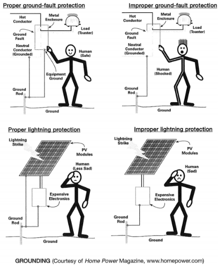
3. Ground-fault Protection
Roof-mounted, DC PV arrays located on dwellings must be provided with DC ground-fault protection (NEC® 2005, Article 690.5). Many grid-tied inverters offer built-in ground fault protection. If a system is to be roof-mounted on a dwelling and the system is not using an inverter package with built-in ground-fault protection, ground fault protection must be wired in separately. Ground-fault protection isolates the grounded conductor (in DC, this is the negative wire) from ground under ground-fault conditions, as well as disconnecting the ungrounded conductor (the positive wire).
Size of Equipment Grounding Conductor
The size of the equipment grounding wire for the PV source circuits, such as the PV to battery wire run; or for grid-tied systems with no battery back up, the PV to inverter wire run, depends on whether or not the system has ground-fault protection.
If the system has ground-fault protection, the equipment grounding conductors can be as large as the current carrying conductors, the positive and negative wires, but not smaller than specified in NEC® 2005, Table 250.122. This table is based on the amperage rating of the overcurrent device protecting that circuit. For example, if the circuit breaker protecting the circuit is rated at or between 30 amps and 60 amps, you can use a #10 AWG copper equipment grounding wire. If the positive and negative conductors have been oversized for voltage drop, the equipment grounding wire also must be oversized proportionally (NEC® 2005, Article Proper ground-fault protection 250.122(b)). From the example in the Wire Sizing Exercise, you increase the necessary wire size from #6 AWG to #1/0 AWG to satisfy a 2% voltage drop requirement. Here you would have to increase your equipment grounding wire from #10 AWG to #4 AWG.
If the system does not have ground-fault protection, the equipment grounding wire must be sized to carry no less than 125% of the PV array short circuit current. For example, if your PV array has a short circuit current of 30 amps, the equipment grounding wire would have to be sized to handle at least 37.5 amps (30 amps X 1.25). Similar to the PV systems with ground-fault protection, if the positive and negative conductors have been oversized for voltage drop, the equipment grounding wire also must be oversized proportionally (NEC® 2005. Article 250.122(b)). From the example in the Wire Sizing Exercise, you increase the necessary wire size from #6 AWG to #1/0 AWG to satisfy a 2% voltage drop requirement. Here you would have to also increase the equipment grounding wire from #10 AWG to #4 AWG .
Size of Grounding Electrode Conductor
The DC system grounding electrode conductor, which is the bare copper wire connecting grounded conductor (the negative wire) and/or equipment grounding conductor to the grounding electrode (the ground rod), cannot be smaller than #6 AWG aluminum or #8 AWG copper or the largest conductor supplied by the system (NEC® 2005, Article 250.166). Even though many PV systems have larger conductors in the system (for example, #4/0 inverter cables), they can use #6 AWG copper wire for the grounding electrode conductor if that is the only connection to the grounding electrode (NEC® 2005, Article 250.166(C)).
Grounding Electrodes
Because all PV systems must have equipment grounding, regardless of operating voltage, PV systems must be connected to a grounding electrode. This is usually done by attaching the equipment grounding wire to a ground rod, via a grounding electrode conductor. PV systems often have AC and DC circuits where both sides of the system can use the same grounding electrode. Some PV systems may have 2 grounding electrodes, which is often the case for pole mounted PV arrays. One electrode is for the AC system and one electrode is for the DC system at the array. If this is the case, these 2 grounding electrodes must be bonded together (NEC® 2005, Article 690.47) with a barrier separating the AC conductors from the DC conductors.
Miscellaneous Code Issues
Stand-alone systems must have a plaque or directory permanently installed in a visible area on the exterior of the building or structure used. This sign must indicate that the structure contains a stand-alone electrical power system, and the location of the system’s means of disconnection (NEC® 2005, Article 690.56). Alternating current and direct current wiring may be used within the same system, although they may never be installed within the same conduit, or electrical enclosures without some type of physical barrier separating the AC conductors from the DC conductors.
Source: “PHOTOVOLTAICS - Design and Installation Manual” by Solar Energy International.
Solar Certification Training from Professional Solar Installers
With 18 IREC-ISPQ Certified Solar Photovoltaic Trainers and 24 NABCEP Certified Solar PV Installers — more than any other solar training organization — Solar Energy International's experienced team is on the forefront of renewable energy education. If you are seeking online solar training or in-person lab training for the NABCEP Entry Level Exam or NABCEP Installer Certification, why not receive your education from a team of the most experienced solar installer professionals in the industry? Many SEI trainers have participated in the most notable solar installations within their communities stateside, and in the developing world.
To start your solar training path today with Solar Energy International, click here.

